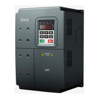
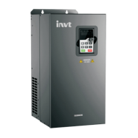
Do you have a question about the INVT GD300L-004G-4 and is the answer not in the manual?
Provides essential safety guidelines for operation, handling, and installation.
Safety measures for delivering and installing the inverter.
Verifies the installation environment meets operational requirements.
Checks performed after the inverter is installed.
Steps for initial configuration and setup of the inverter.
Lists the technical specifications of the inverter.
Details the rated electrical and performance specifications.
Details on physical mounting and environmental requirements.
Specifies the required environmental conditions for installation.
Guidelines on how to orient the inverter during installation.
Instructions for connecting power and control wiring.
Illustrates the main circuit wiring for different inverter models.
Illustrates the wiring for the inverter's control circuit.
Measures to protect wiring and components from electrical faults.
Instructions on how to operate the inverter using the keypad.
Steps to change inverter parameters.
Parameters related to starting and stopping the motor.
Parameters specific to motor configuration and characteristics.
Parameters for vector control mode operation.
Parameters for configuring acceleration/deceleration (S-curve) profiles.
Parameters for various protection functions.
Illustrates wiring for multi-step and analog speed modes.
Lists essential parameters to configure before commissioning.
Steps to test and fine-tune the inverter and motor operation.
Procedure for automatically tuning motor parameters.
Fine-tuning S-curve parameters for smooth acceleration/deceleration.
Fine-tuning parameters to ensure accurate floor leveling.
Details on multi-step speed operation with brake and contactor control.
Parameters and operation for distance-based control.
Procedure for resetting faults.
Lists common inverter faults, their causes, and solutions.
Provides diagnostic flowcharts for common inverter issues.
Flowchart for diagnosing motor startup problems.
Flowchart for diagnosing overcurrent faults.
Information about the Safe Torque Off function.
Details on STO function logic, channels, and installation.
Details inverter capacity and power ratings.
Provides specific dimensions for mounting inverters by model.
Shows the wiring diagram for GD300L series peripherals.
Table of recommended cable sizes and tightening torques.
Guidance on selecting braking components.
How to choose braking resistors or units.
Table of braking resistor/unit selection.
| Model | GD300L-004G-4 |
|---|---|
| Output Power | 4 kW |
| Overload Capacity | 150% for 60 seconds |
| Frequency Range | 0-400 Hz |
| Control Mode | V/F control, Vector control |
| Cooling Method | Forced Air Cooling |
| Storage Temperature | -20°C to +60°C |
| Humidity | 5% to 95% (non-condensing) |
| Enclosure Rating | IP20 |
| Communication Interface | RS485 |
| Type | Inverter |
| Input Voltage | 3-Phase 380V (-15%) - 440V (+10%) |
| Output Voltage | 3-Phase 0-Rated Input Voltage |
| Rated Output Current | 9.0 A |
| Protection Features | Overcurrent, overvoltage, undervoltage, overload, overheating, short circuit |
| Operating Temperature | -10°C to +50°C |
| Altitude | Below 1000 m |
| Efficiency | ≥98% |


