Goodrive300-LIFT series inverter Commissioning guidelines
-77-
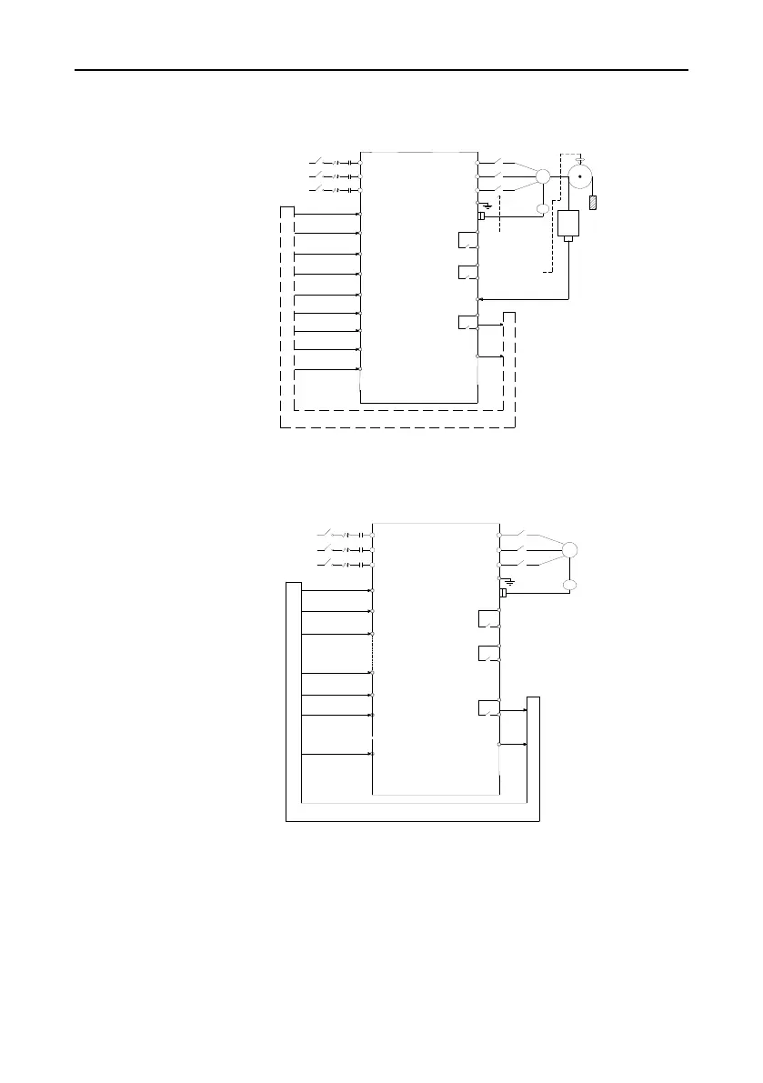
7.2 Wiring between the lift controller and inverter
7.2.1 Wiring for the multi-step speed running mode
R
S
T
S1
S2
S3
S4
S5
S6
S7
S8
HDI(S9)
W
V
U
PE
Y1
LR
EO
KM1
Maintenance
Brake feedback
Contactor feedback
Multi-step speed 3
Multi-step speed 2
Multi-step speed 1
Enable
Down
Up
Fault output
RO1
RO2
RO3
Weigh AI1 input
FC(brake
control)
TC(contactor
control)
Car
PG
M
KM2
GD300L inverter
special for lifts
3PH
380V-15%
~440V+15%
50/60Hz
Lift controller
FWD
REV
ENA
MS1
MS2
MS3
TB
FB
EXM
Figure 7-2 Typical wiring for the multi-step speed running mode
7.2.2 Wiring for the analog speed running mode
Lift controller
3PH
380V-15%
~440V+10%
50/60Hz
GD300L inverter
special for
lifts
KM2
M
PG
TC(contactor
control)
FC(brake
control)
RO3
RO2
RO1
Fault
output
Enable
Up
Down
Maintenance
Contactor feedback
Brake feedback
KM1
EO
LR
Y1
PE
U
V
W
AI1
FB
TB
EXM
REV
FWD
ENA
T
S
R
Speed command
S1
S2
S3
S7
S8
HDI(S9)
SPD
Figure 7-3 Wiring for the analog speed running mode
7.3 Setting basic parameters
After correct wiring, set application parameters as required. Pay high attention to the parameters
related to peripheral electrical wiring, such as operation mode, control mode, programmable
input/output setting, and feedback selection. Perform commissioning only after these parameters are
correctly set. The table below lists the basic parameters.
 Loading...

