Goodrive300-LIFT series inverter Function parameters
-66-
Detailed instruction of parameters
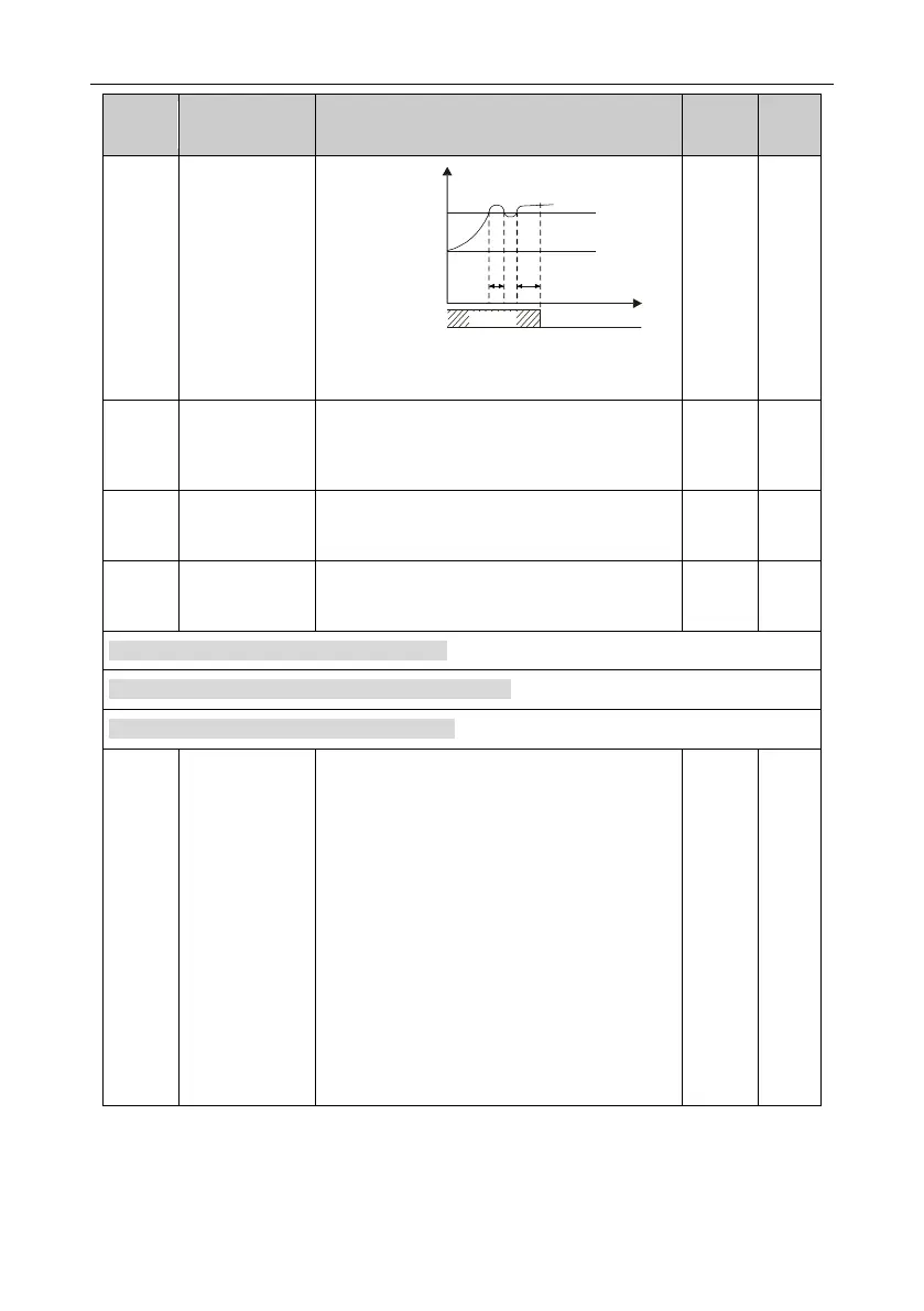
Speed
Actual detected
value
Set detection
threshold
Time t
t1
t2
t2=P11.14
t1<t2, so the inverter continues running
Running Fault output dEu
Emergency
operation
undervoltage
point
Operation when
no enabling
signal is found
0: Immediately report the fault and stop
1: Report the fault after stop
Enabling signal
delay detection
time
0.0–10.0s (running time before an enabling
signal delay is detected)
P12 Group Motor parameters 2 (reserved)
P13 Group Synchronous motor control (reserved)
P14 Group Serial and CAN communication
Local
communication
address
Setting range: 1–247
If the slave communication address is set to 0
when the master is writing the frame, the
address is the communication address. All
slaves on the MODBUS fieldbus can receive the
frame, but the salves do not answer.
The local communication address is unique in
the communication network. This is the
fundamental for the point to point
communication between the upper monitor and
the inverter.
Note: The slave address cannot set to 0.
 Loading...

