Goodrive300-LIFT series inverter Commissioning guidelines
-86-
Running sequence description:
1. After receiving the FWD and MS1–MS3 commands from the controller, the inverter sends the
contactor close command and outputs the running signal.
2. With the delay of T2 after receiving the running command, the inverter starts to accelerate to
the start frequency set in P01.01.
3. After accelerating from the start frequency to the braking frequency (P08.14), the inverter
sends the brake open signal with the delay of T3 (P08.05, brake open delay).
4. After the brake is open, the inverter accelerates to the reference speed.
5. After the controller switches off the speed command (MS1–MS3), the inverter decelerates to
stop according to the S curve. When the frequency reaches P08.14 (stop braking frequency),
the inverter outputs the brake close command with the delay of T4 (P08.04, brake close delay),
requiring the controller to remove the running command.
6. After receiving the stop command sent by the controller, the inverter stops output with the delay
of T5 (P08.15), and the running signals are cancelled. After the delay of T6 (P08.28), the
contactor is opened, and the running process ends.
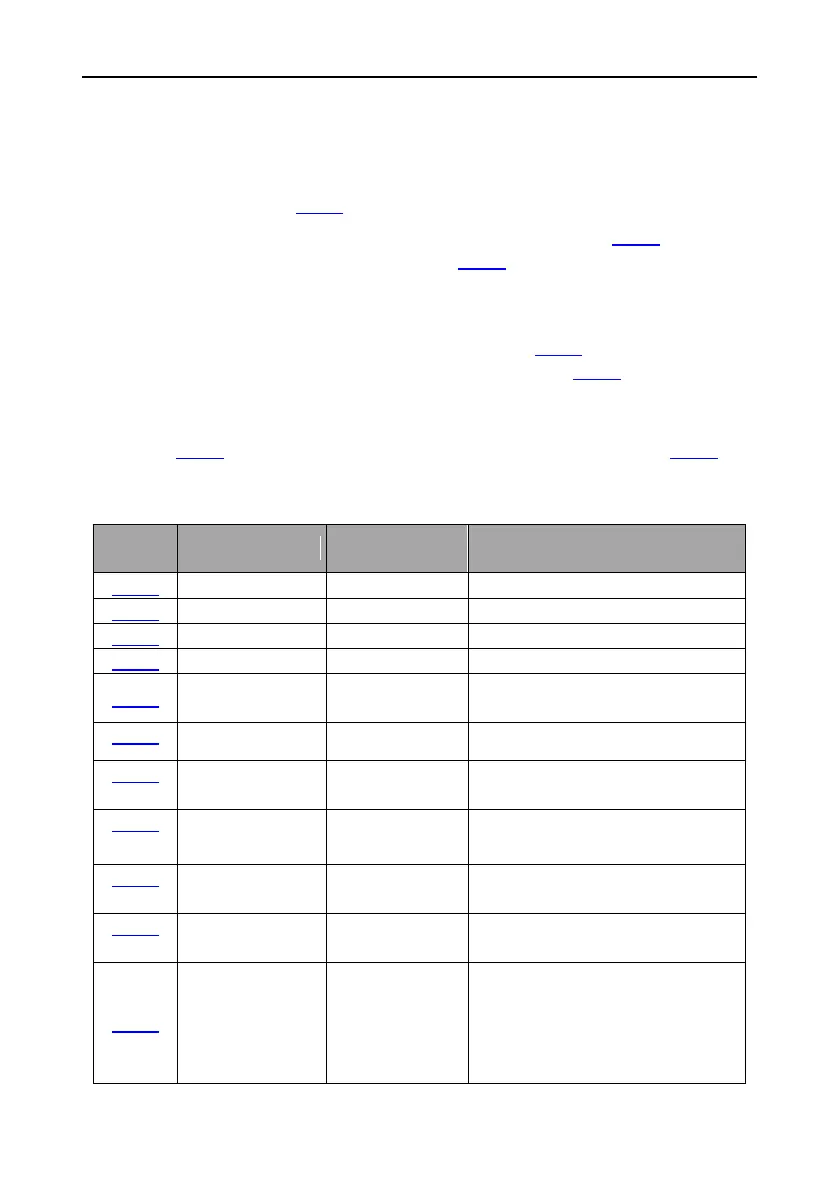
The table below lists the typical function codes for open-loop running.
Pre-start braking
current
Start frequency in
stop braking
Stop knee-point
frequency
Generally, the speed is consistent with
the leveling speed. It is usually used to
switch the stop curve. After the speed
decreases to this point, the stop curves
switches to the stop S curve.
 Loading...

