iPECS eMG80
Hardware Description and Installation Manual Issue 1.0
26
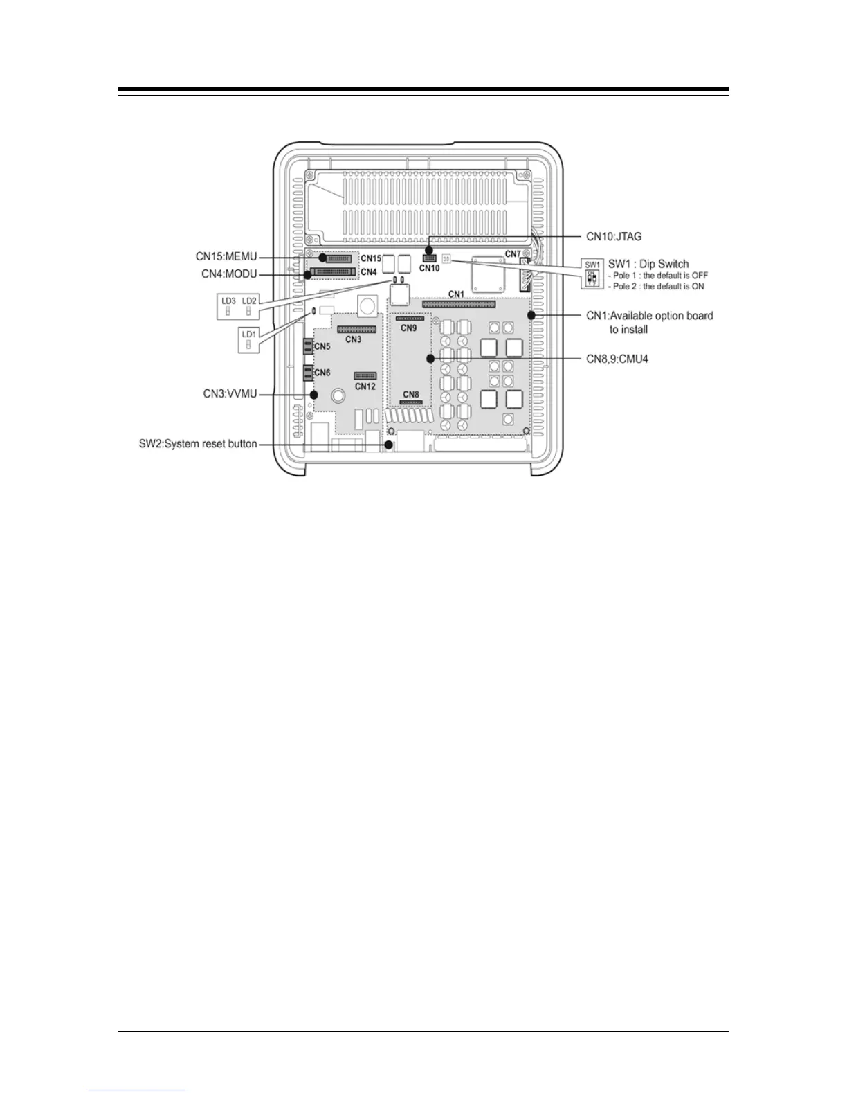
Figure 4.5.1-1 MBUA
The following are included on the MBUA:
4 CO Line interface circuits
1 DKT (Digital Key Telephone) interface circuit for Attendant station 100
7 Hybrid (DKT or SLT) interface circuits
1 External Relay contact for LBC or general purpose
1 Alarm detection circuit, External Page port, and External MOH port
Internal MOH (13 music resources)
Built-in VoIP channels (default 2 channels, maximum 8 channels with license)
Built-in VM channel (default 2 channels, maximum 4 channels with license)
Master Clock Generation & PLL circuit
1 PFT circuit [CO1 connects to the last SLT port (STA8)]
1 RS-232C Interface circuit
1 LAN Interface
1 USB interface circuit
PCM Voice Processing circuit (ACT2 - ASIC, voice switching, including DSP)
- PCM Tone Generation and PCM Gain Control
- Tone (DTMF / CPT / FAX) detection and CID Signal (FSK/DTMF/RUS CID)
detection
NOTE
When AC Power was failed, the last SLT port on MBU will be connected to CO1
automatically.
 Loading...