iPECS eMG80
Hardware Description and Installation Manual Issue 1.0
84
7.3.2 SLT Wiring
SLTs are wired to the center pair of the RJ11 jack, typically on the bottom or back of the
SLT. The wall outlet should be connected to an appropriate SLT port in the eMG80 system.
1. Wire the center pair of the wall outlet to the termination point using UTP cable.
2. Using the line cord provided with the SLT, connect the SLT to the wall outlet.
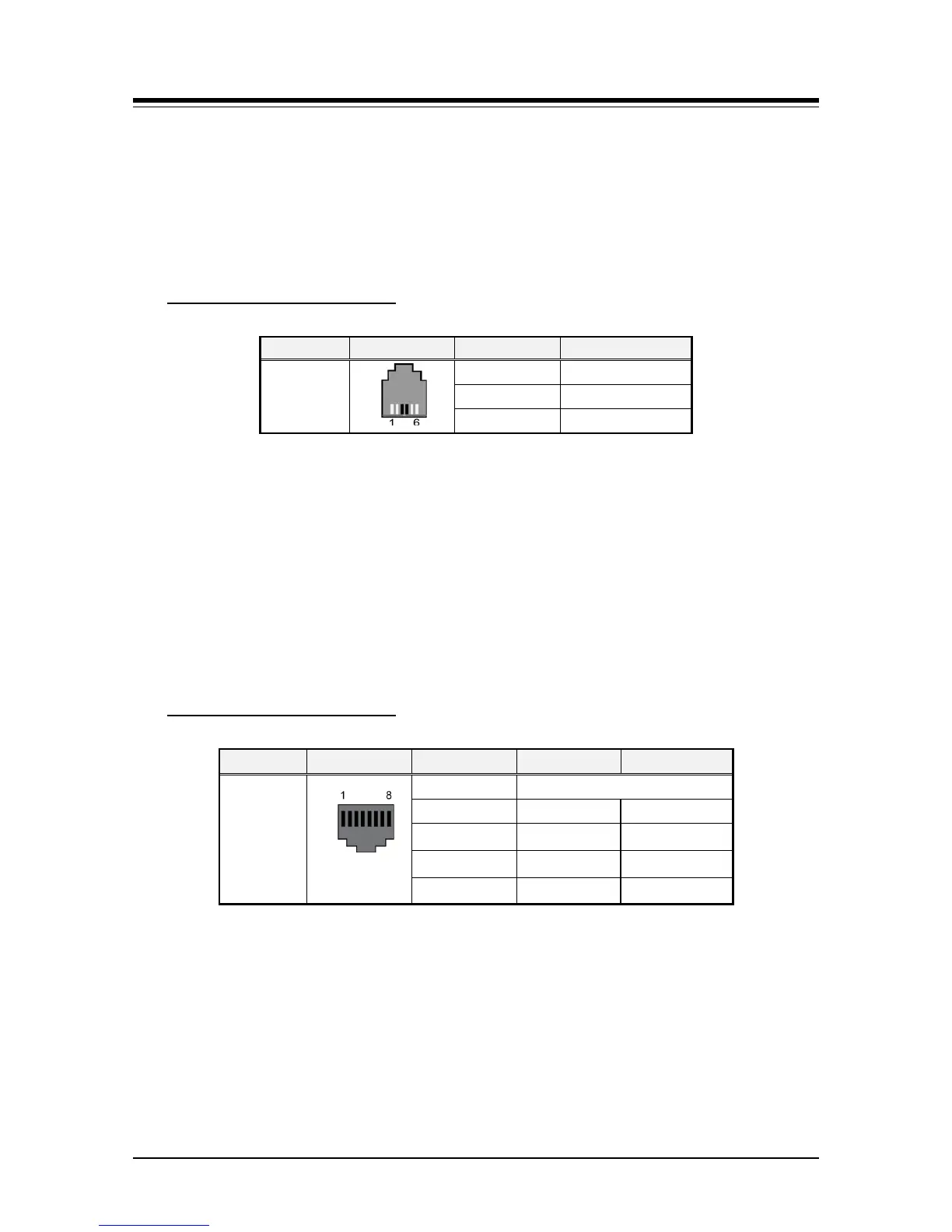
Table 7.3.2-1 SLT Modular Jack Wiring
Modular Jack Pin Assignment
RJ11
1,2 N/A
3,4 TIP, RING
5,6 N/A
7.3.3 IP Phone Wiring
The iPECS eMG80 supports the LIP-8000E series IP Phones. LIP-8000E series phones
include two (2) Ethernet ports, a LAN port and a PC port. The LAN port is connected to an
Ethernet switch port and the PC port is connected to the LAN connection of a PC. The LIP
phones are wired to any 10/100/1000 Base-T Ethernet switch port with access to a VoIP
channel of the eMG80. The LIP phones can be powered from a POE Class 2 compatible
Ethernet switch port or using the AC/DC Adaptor-K.
Table 7.3.3-1 LIP Phone Modular Jack Wiring
Modular Jack Pin Assignment
Connector Pin-out Pin Number Signal Name
Function
RJ45
4,5,7,8 Reserved
1 TX+ Transmit Data
2 TX- Transmit Data
3 RX- Receive Data
6 RX+ Receive Data
1. Using the above wiring chart, wire the RX and TX pins from the RJ45 Wall outlet, or
equal, for the IP Phone to the appropriate Ethernet switch termination point using
Cat 5 or, for 1000 Base-T Cat 5e UTP cable. The maximum wire length between the
IP Phone and the Ethernet switch port is 100 meters or 328 feet.
2. Use the RJ45 terminated cable provided with the phone to connect the IP Phone
LAN port to the Wall outlet.
3. Connect the PC port to a PC LAN port using a CAT 5 cable terminated on each end
with an RJ45 connector.