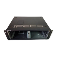
iPECS eMG80
Hardware Description and Installation Manual Issue 1.0
39
The following chart lists the various connectors for option boards, RJ modular jacks for
connecting CO Lines, Stations and miscellaneous functions, and switches on the Main
Board.
Connectors, Jacks and Switches
Table 4.6-1 EKSU with EMBU Connector, Modular Jack and Switch Function
CN1 CO and Extension board installation 70 pins
CN5 & CN6 Connection KSU to EKSU with Expansion cable 19 pins x 2
CN8 & CN9 MG-CMU4 Installation 8/10 pins
MJ1
2 ports each
3/4 CO line
MJ2 8 Hybrid DKT or SLT ports 8 ports
MJ4 Relay/Alarm 1 port
Table 4.6-2 EMBU LED Indication
LED Indications
LD1 Blue Flash 300ms ON and OFF, normal operation toggle
LD2 Blue Station port in use status
ON - A station is in use
OFF - All station are idle
 Loading...