42
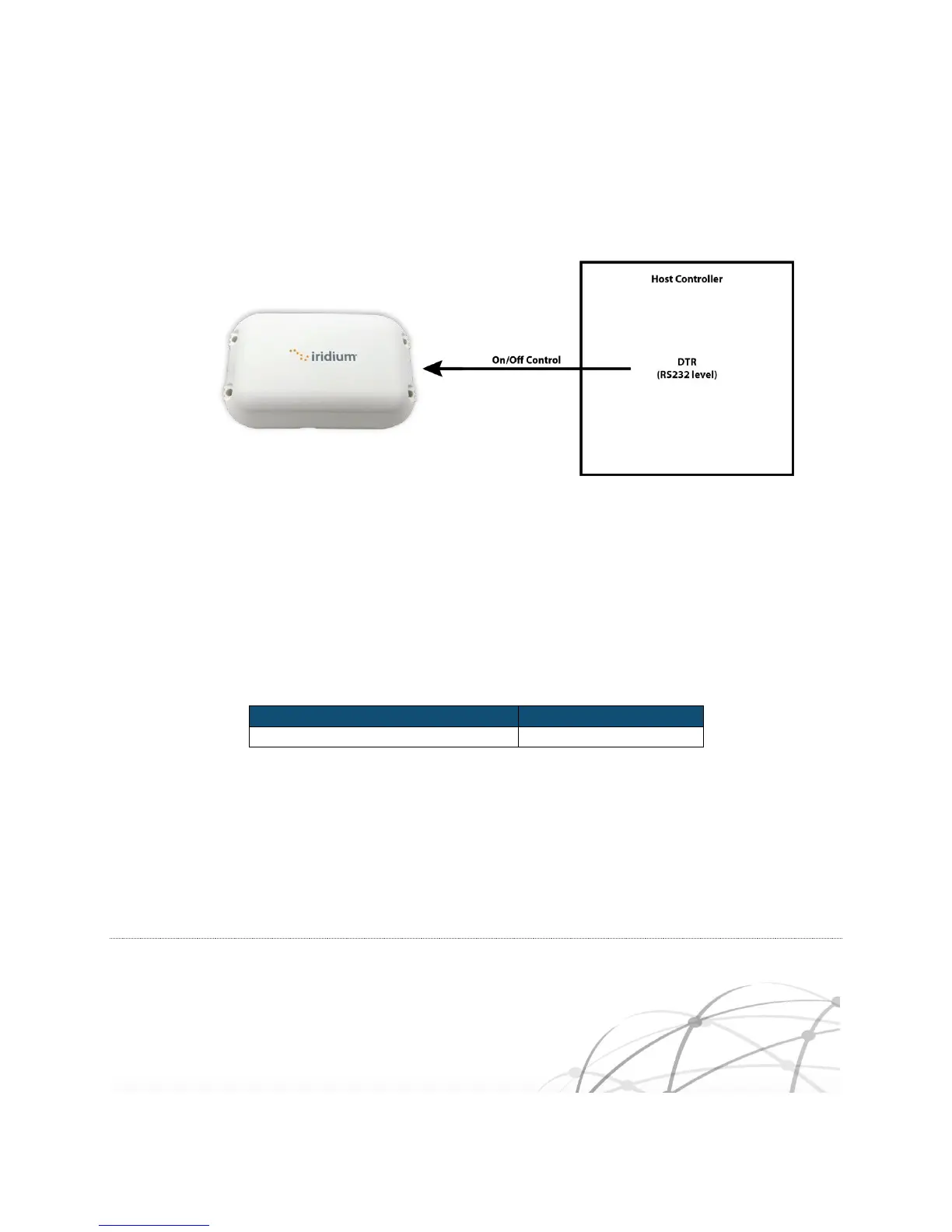
Alternatively, the On/Off control line can be driven directly by a RS232 signal level such as DTR.
Figure 3-2 On/Off Using DTR
Prior to turning off the Iridium Edge, a “flush memory” (AT*F) command should be issued to ensure all
internal SBD modem’s flash memory write activity is completed.
3.3.2 Power Down Consumption
The table below shows typical average current draw when the Iridium Edge is powered down.
Table 3-13 Power Down Specifications
3.4 Network Available Indicator
The Iridium Edge’s Network Available (pin #7) indicator is driven directly by the internal SBD modem.
When active, the Network status indicates if the Iridium Edge has visibility to an Iridium satellite. As an
alternative to using the Network Available hardware output, a host can use AT commands to poll the