I A P 2 0 2 3 . 0 0 1 - A F M / I R I S T E X A N I I P A G E | 28
FOR SIMULATION USE ONLY – NOT A TRAINING AID
Start and Ignition System
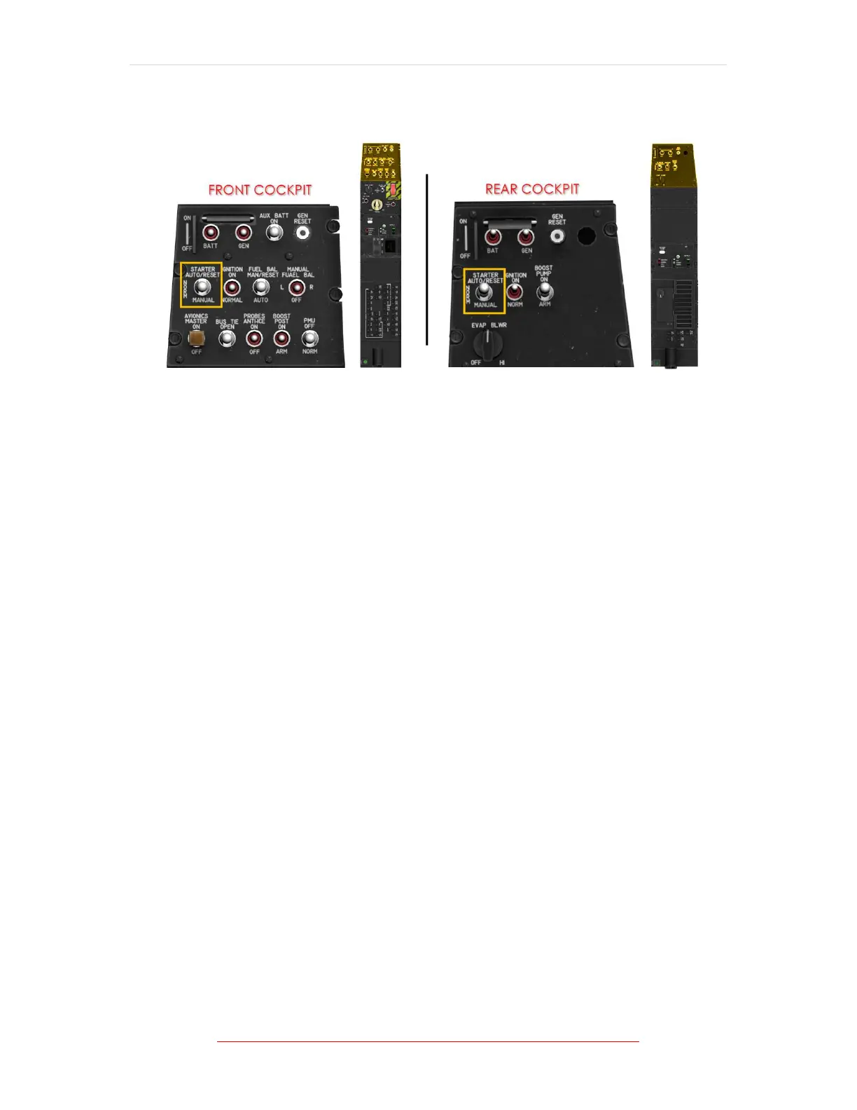
Figure 1-8 Starter Switch Location/s
The STARTER switch, located in both cockpits has three positions: AUTO/RESET,
NORM, and MANUAL.
To select MANUAL, the STARTER switch must be lifted over a detent to the MANUAL
position.
Selecting MANUAL will engage the starter until the switch is manually moved back
to the NORM position.
From the NORM position, AUTO/RESET may be selected by moving the switch
forward.
The switch is spring loaded to return to the NORM position.
Momentarily placing the starter switch in the AUTO/RESET position automatically
engages the starter and energizes the ignition system. Power for the start control
is provided through a circuit breaker, placarded START, located on the battery bus
circuit breaker panel in the front cockpit.
The IGNITION switch, located in both cockpits, has two positions: NORM and ON.
During an auto start or normal operation with the ignition switch set to NORM, the
PMU will energize and de-energize the igniters as required.
When the IGNITION switch is set to ON or when the igniters are activated in AUTO
mode, a green IGN SEL advisory is illuminated. Power for the ignition system is
provided through a circuit breaker, placarded IGN, located on the battery bus circuit
breaker panel in the front cockpit.