I A P 2 0 2 3 . 0 0 1 - A F M / I R I S T E X A N I I P A G E | 29
FOR SIMULATION USE ONLY – NOT A TRAINING AID
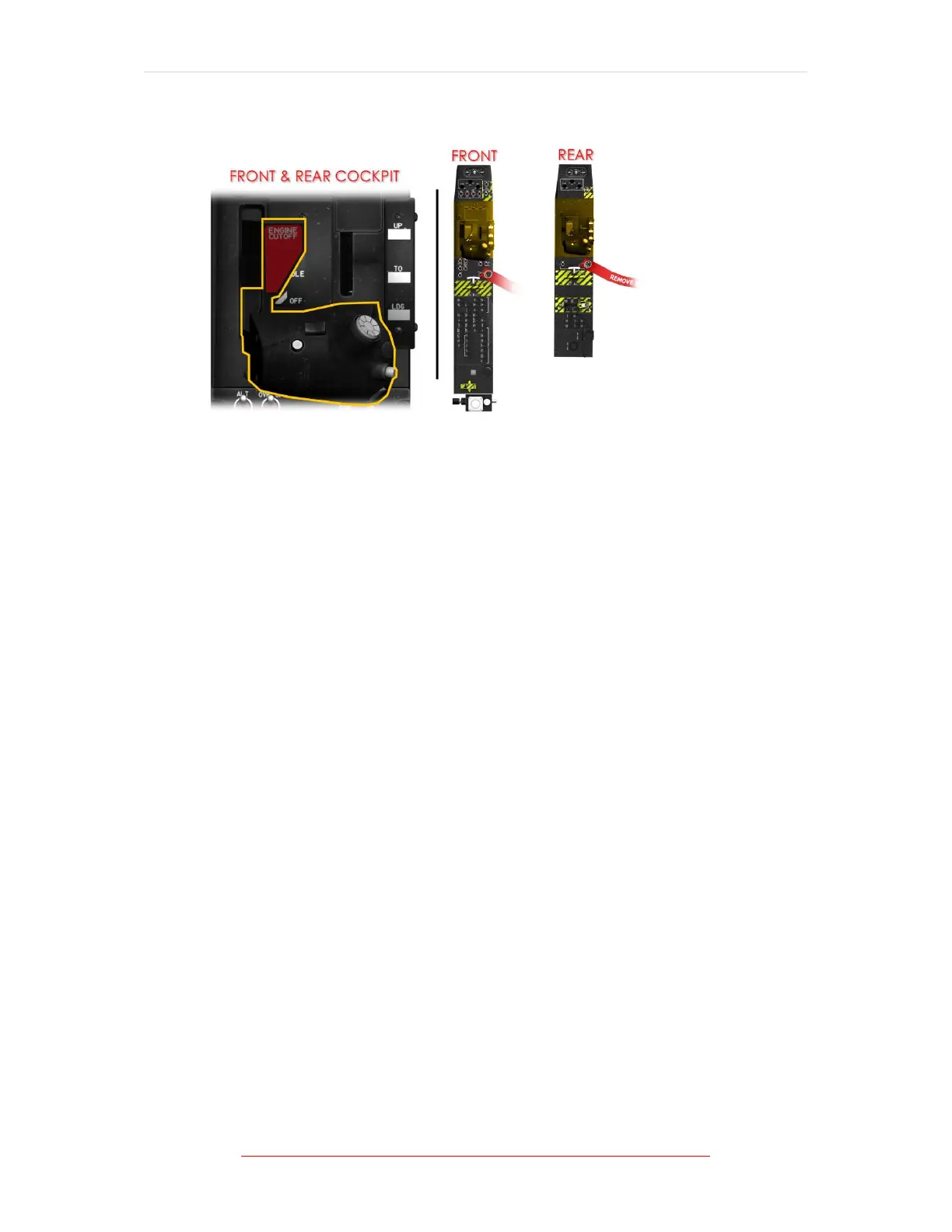
Power Control Lever (PCL)
Figure 1-9 Power Control Lever (PCL) Location/s
Engine power is controlled by the PCL mounted in the left console of each cockpit.
The PCLs are interconnected with a push-pull rod so that movement of one PCL
moves the other.
The front PCL is connected to the fuel management unit (FMU) both electrically and
mechanically with a flexible cable. Friction adjustment is provided in the front
cockpit only.
The PCL incorporates a cut-off gate to prevent inadvertent engine shutdown.
When the PCL is moved forward to idle during engine start, two roller bearings lock
in place on the front side of a rocker cam detent to secure the gate.
Each roller bearing makes an audible click as it locks in place. Lifting the cut-off
gate handle moves the rocker-cam out of the way and allows the PCL to move to
the cut-off position.
The PCL in each cockpit contains switches for activating the speed brake, rudder
trim, UHF and VHF communications, and intercommunications system.
Power Management Unit (PMU) Operation
A dedicated permanent magnet alternator (PMA), mounted on the reduction
gearbox, powers the PMU. The PMA supplies 32 VAC, which the PMU converts to DC.
The PMU automatically switches to the 28 VDC battery bus when propeller RPM
drops below 40-50% Np, or when the PMA fails.
The PMU operates in either flight or ground mode. The aircraft weight-on-wheels
switches on the main gear struts control these modes. In ground mode, idle is 60%
N1 and in flight mode, idle is approximately 67% N1. Above 10,000 feet PA, the PMU