-
CONTINUED
HOOKING UP THE VALVES
A maximum load of 30VA ( 1.24 amps) may he connected to
each station. A maximum total load of 43 VA (1.8 amps) may he
programmed to operate simultaneously.
1.
Strip the solenoid wires approximately
l/4
inch (do not
bend
exposed end).
2.
Following the wiring diagram in figure 1, insert straight hare wire
between the plates of the “sure grip” terminal. Connect one
solenoid wire to the station terminal and the other to common.
R
Tighten screw firmly.
CAUTION:Use a separate (dedicated) valve common wire for each
controller. DO NOT daisy-chain
controllers
together
using the same common wire.
3.
Before turning on the power, recheck all
leads
connected to the
terminal block for shorts.
TESTING THE VALVE HOOK-UPS
1.
Make sure the valve common wire and all station wires
are connected.
2.
Turn
on power to the controller.
3.
Turn dial to Station Test position.
4.
To enter test time, key in a number from 1 min. to
9
min.
If no time is entered, 2 min. will be assumed.
5.
Press the Manual On/Off key.
Each station in sequence will
turn
on for the number of minutes you
entered. A Fused Circuit test will occur
during
the station test.
If a Fused Circuit condition exists on any station, the controller
will display “FUSE” alternately with the station number. “FUSE”
indicates a short on that station. See “How the Electronic Circuit
Breaker Works”, page 7.
-
CONTINUED
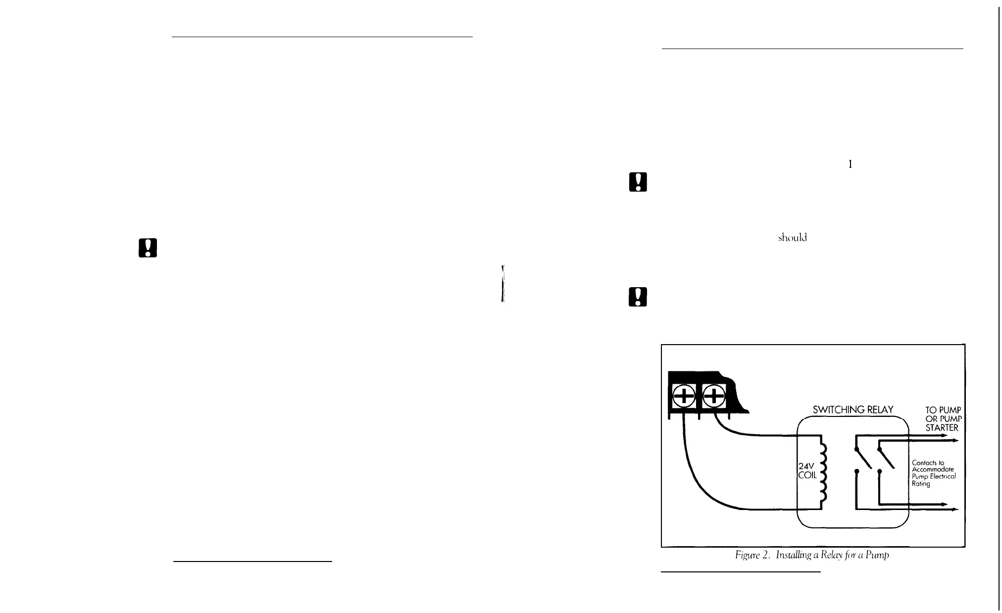
IF YOU HAVE A PUMP
In cases where a pump is
to
he
controlled
by the
master
valve
output,
DO NOT drive the pump directly from the controller. The master
station must he connected
to
the coil of a 24 VAC relay, such as an
Essex #l84-20105-101Z
(I ‘itrol
p
Irr
number
I
100 1).
El
CAUTION:
Connecting pump to
controller without a 24 VAC
relay
will
damage
controller.
The pump latch relay should he set up by
an
electrician
so
that
a
switch
closure will
activate
the latch relay coil, turning on the pump. The
switch
contacts
of
the relay
should
he connected to control the latch
relay coil (see figure 2). The relay should he mounted
at
least
5
feet
from
the
controller
box, and the box MUST be
grounded.
Installation
must follow all local electrical wiring codes.
g
CAUTION:
DO
NOT
attempt
to
power the controller using
power from one phase of pump
power.
This will
damage the controller.
VALVE MASTER
COMMON VALVE
PUMP
-
POWER
4
Installing and Wiring the Controller
Installing and Wiring the Controller
5