Installing the Controller Cabinet
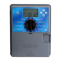
Select a sheltered location for the indoor model Rain Dial-R such as
a garage or service room, preferably within 5' (1.5m) of a grounded
electrical outlet. For outdoor controllers, choose a location that protects
against direct exposure to sun and contact with irrigation spray, and is at
least 5' (1.5m) away from any motorized equipment.
1. Drive the provided stainless steel screw into a wall stud at approxi-
mately eye level, leaving 1/4" (6.4mm) of the screw shaft exposed.
Note: Use screw anchors when installing on drywall or masonry.
2. Hang the controller on the screw using the keyhole-shaped slot.
3. To secure the controller, drive one or two screws through the lower
mounting holes.
Note: The lower mounting holes in the Outdoor cabinet have a thin
veneer that is easily pierced when installing the mounting screw
during installation.
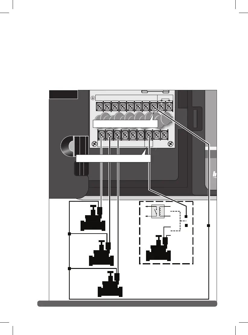
Connecting the Valve Control Wiring
For best results, use connection wire cable specifically designed for
automatic irrigation systems. Use 18-AWG wire for connections up to 800'
from the controller, or heavier 14-AWG (2.0mm2 ) wire for connections
up to 2000'. A separate wire for each valve (and relay) connection and at
least one common (return) wire is required.
Note: If control wire conduit is required, install it at this time. For
conduit installation, use the 3/4" (19mm) access hole in the indoor
cabinet, or the threaded 1.25" NPT opening in the outdoor cabinet.
1. Route the control wire from the controller location to the valve(s).
2. Attach a separate control wire to either lead of each valve solenoid.
3. To provide a common (return) wire, attach the remaining lead of
each valve solenoid to a single wire.
Note: To prevent corrosion and a possible short circuit, use
waterproof wire connectors on all external wire splices.
For reference at the controller, note the wire color used for each
valve connection and its corresponding watering zone.
4. Route the cable through the largest opening in the base of the
controller cabinet or through conduit if installed. Remove the
cable jacket to expose about 8" of wires. Carefully remove 3/8" of
insulation from the end of each wire to be connected.
5. Secure each valve wire to numbered terminal in the preferred
operating sequence order.
6. Connect the common wire to the terminal labeled “VC.”
7. If applicable, connect one leg of the master valve or pump start relay
to the valve common wire.
at 0.375A maximum.
 Loading...