32
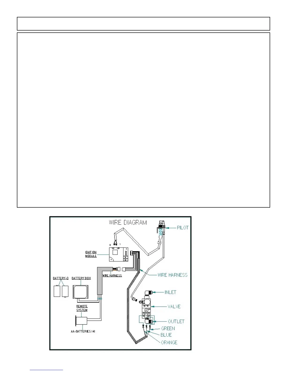
SafetyInstructionsPriorToInstallation/PilotAssemblyWireDiagram
ISOFLAMES FIREPLACE WIDTH FIREPLACE HEIGHT BTU NATURAL GAS BTU LIQUID
BURNER MINIMUM PROPANE
24” IBV 36” 30” 50,000 50,000
30” IBV 46” 30” 65,000 65,000
8. Gas supply pressures:
GAS SUPPLY PRESSURE NATURAL GAS LIQUID PROPANE
Minimum inlet gas supply pressure for the purpose of input adjustment 5” w.c. 10.5” w.c.
Maximum inlet gas supply pressure 7” w.c. 13” w.c.
Manifold pressure 3.5” w.c. 10” w.c.
The ISOFLAMES gas log system’s gas control valve must be disconnected from gas supply piping system during any pressure
testing of the ISOFLAMES gas log system at test pressures in excess of 1/2 psi (3.5kpa). The ISOFLAMES gas log system must
be isolated from the gas piping system by closing the gas control valve during any pressure testing of the gas supply piping system
at test pressures less than 1/2 psi (3.5kPa).
9. All ISOFLAME gas log assembly systems (whether with Safety Pilot Valve or Remote Pilot Valve) are equipped with a 1/8 NPT
plugged tapping, accessible for test gage connection, immediately upstream of the gas supply connection to the appliance.
10.TheISOFLAMESgaslogsareconvertibleifdonebyacertiedgastechnician.
11.KeeptheISOFLAMESgaslogsystem’sareaclearandfreefromcombustiblematerialssuchasgasolineandotherammable
vapors and liquids.
12.DonotusetheISOFLAMESgaslogsystemifanyparthasbeenimmersedinwater.Callaqualiedservicetechnicianto
inspect the ISOFLAMES gas log system. Replace any part of the ISOFLAMES gas log system that has been immersed in water.
13.Thereplacechimneyandueneedstobeinspectedandcleanedonceayearbyaqualiedservicetechnician.
 Loading...