Isokern Gas Burner Installation Instructions
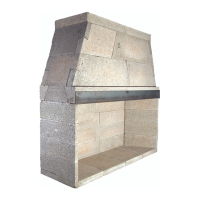
Fig. 1 - Burner System Detail - Bottom View
1. MAKE SURE THE FIREPLACE GAS SUPPLY IS
TURNED OFF.
2. Place the burner system in the fi replace. Rest it
upward, on the front grate fi ngers to expose and
allow access to the bottom rear of the burner
controls.
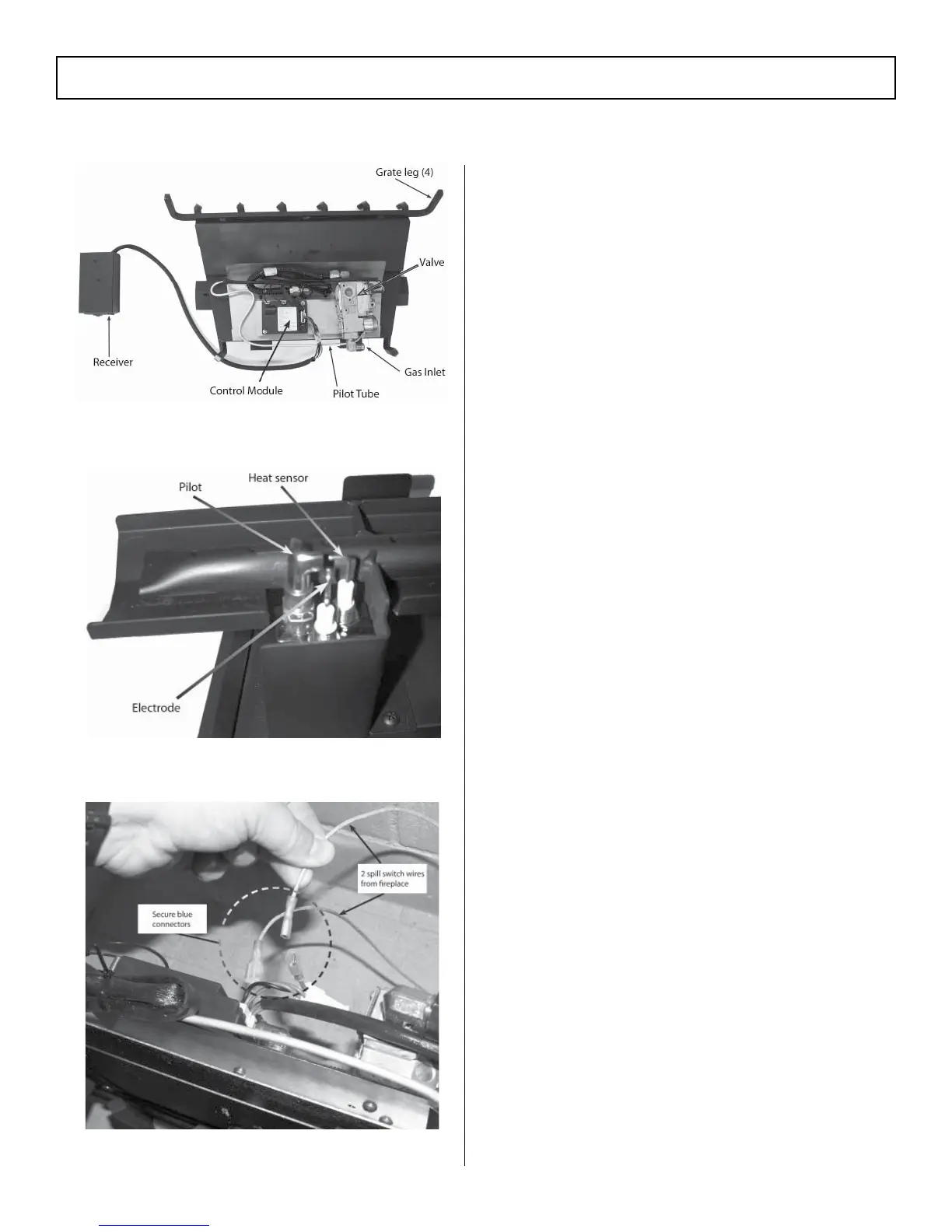
3. Locate the two spill switch wires coming out of
the hole in the lower right side of the fi replace.
Connect the spill switch wires to the two free wires
(coming from the control module) located at the
rear of the burner system (see Fig. 3).
4. Place the burner system down so that it rests on
the burner grate legs. Center the burner toward
the rear of the fi replace. (Reference Fig. 5 for
orientation.)
5. Locate the gas-supply stub inside the fi replace
and remove the cap, if attached (see Fig. 4).
6. Use pipe compound resistant to all gases or Teflon
tape to attach the supplied elbow to the gas-supply
stub. Then attach the fl ex connector (coming off
of the burner system) to the elbow (see Fig. 4).
Fig. 2 - Burner System Detail - Pilot Assy
Fig. 3 - Connect spill switch wires
 Loading...