System-Related Functions
Copyright ©ITECH Electronic Co., Ltd. 63
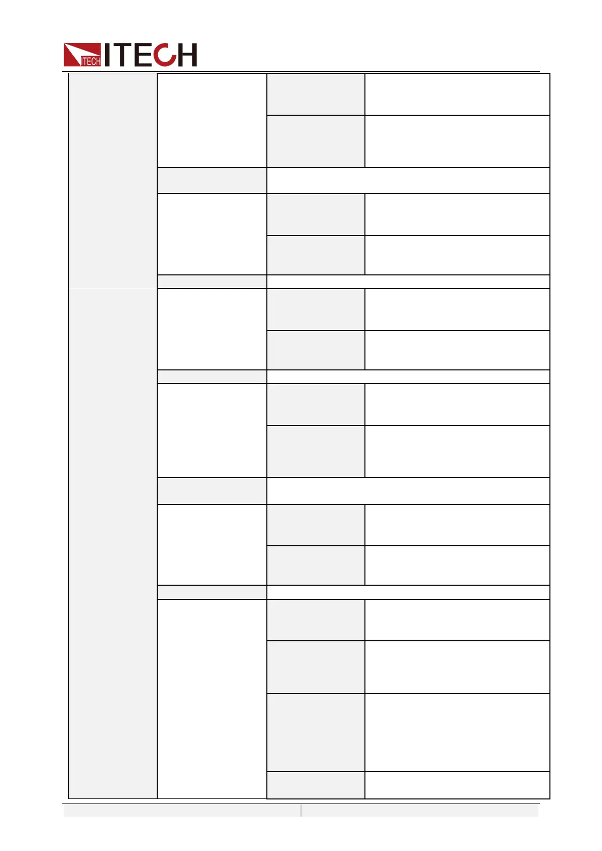
On/Off, Select Invert or not under the
IO Settings. If setting to ON, it means
the valid signal is reversed.
⚫ Inhibit-living:
⚫ Inhibit-latch
⚫ Input
⚫ Output
Function setting of pin 2
On/Off, Select Invert or not under the
IO Settings. If setting to ON, it means
the valid signal is reversed.
⚫ PS Clear
⚫ Input
⚫ Output
Function setting of pin 3
On/Off, Select Invert or not under the
IO Settings. If setting to ON, it means
the valid signal is reversed.
Function setting of pin 4
On/Off, Select Invert or not under the
IO Settings. If setting to ON, it means
the valid signal is reversed.
⚫ Sync-in
⚫ Sync-out
⚫ Input
⚫ Output
Digital IO-5:
ON/OFF Status
Function setting of pin 5
On/Off, Select Invert or not under the
IO Settings. If setting to ON, it means
the valid signal is reversed.
⚫ ON/OFF Status
⚫ Input
⚫ Output
Function setting of pin 6
On/Off, Select Invert or not under the
IO Settings. If setting to ON, it means
the valid signal is reversed.
⚫ Trigger1-out
⚫ Trigger1-in
⚫ Input
⚫ Output
On/Off: When On is selected, a trigger
signal is output when AC amplitude
changes. The accuracy of voltage change
is 100mV and is not restricted by phase.
(This configuration is displayed only
when the IO pin is set to Trigger1-out)
On/Off: When On is selected, a trigger
signal is output when the DC amplitude