Operation: Base Metrology
20 CENTRON® Meter Technical Reference Guide
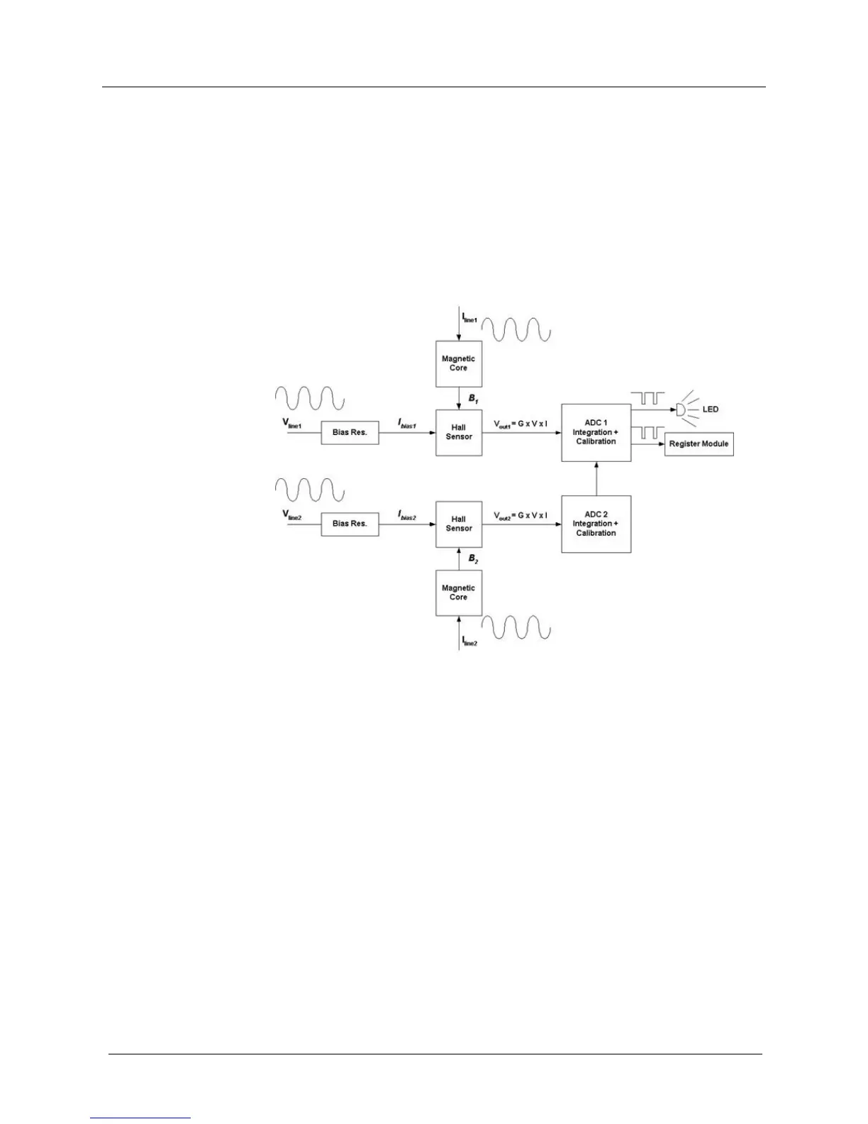
Each Hall sensor output voltage is amplified by a differential amplifier in order to bring the
signal within the nominal level of the ADC. ADC 1 sums the signal from ADC 1 and ADC
2. The output of ADC 1 is integrated over time to get the energy information. Each time the
integrated signal exceeds a predetermined amount of energy, a pulse is generated. The pulse
stream is accumulated into a counter. When the accumulated pulses reach a threshold, a Wh
pulse is emitted and the meter LED is flashed. The counter threshold is programmed at the
factory and serves as the permanent gain calibration for the life of the product. The
calibration is a digital feature and has no variation or adjustment. ADCs 1 and 2 are
calibrated independently, which means that each phase is calibrated independently.
Figure 15: Hall Cells and ADCs