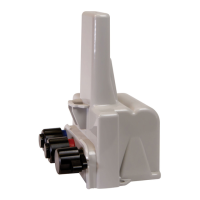
1. Push the hollow pin (1) completely out of its location and separate the 500WERTModule
mounting bracket (2) from the meter register collar (3).
2. Strip 1/2 inches of insulation from the end of the brown, gray, and yellow wires.
3. Place the 500WERTModule on the mounting bracket and route the yellow, gray, and
brown wires through the opening.
Note: A gasket is not required.
4. Install four Torx-head mounting screws (Itron part number SCR-0010-005).
5. Hand-tighten each screw.
6. Connect the 500WERTModule wires to the register screw terminals following the
500WERTModule to the Elster/AMCO meter register wire connections.
Caution: Install the wires around the screws in a clockwise direction (as shown) or the wires may
come out from under the screw heads as you tighten them. Also, verify that insulation is NOT
compressed under the screw head, or the wire may not make good contact.
Gen5 500WERTModule Remote Installation Guide 3 Setting up and Installing
December 5, 2022 LDI-0343 REV002 Itron, Inc. Page 22 of 48

 Loading...