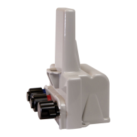
Caution: A vertical mounting position is important to maximize RF performance. Mount the
500WERTModule with the module's label arrow pointing up. The module's arrow must never point
to either side or upside down. The module's tilt tamper functionality is designed to operate with the
module installed vertically.
1. Remove the pipe bracket and band clamp from the pipe mount kit (Itron part number CFG-
0005-003). Pipe brackets may be black or gray. These instructions show a black pipe
bracket.
2. Loosen the band clamp screw until the end of the band releases.
3. Push the end of the clamp's band through the holes in the pipe bracket.
4. Place the band clamp around the pipe. The band loosely wraps around the pipe.
5. Push the end of the band through the band clamp screw assembly. Turn the band clamp's
screw assembly to fit into the pipe bracket opening. Tighten the clamp screw until the band
clamp is secure on the pipe.
Adapter Plate Mounting Positions
The installation procedure in the previous section shows how to mount the adapter plate
on a vertical pipe.
The following pictures show the adapter plate on 45-degree angle and horizontal pipes.
Regardless of the angle of the pipe, the adapter plate mounting lug (1) must always be at
Gen5 500WERTModule Remote Installation Guide 3 Setting up and Installing
December 5, 2022 LDI-0343 REV002 Itron, Inc. Page 26 of 48

 Loading...