EasyManuals Logo

ITRON SHARPFLOW SWB7 User Manual

ITRON SHARPFLOW SWB7
32 pages
To Next Page IconTo Next Page
To Previous Page IconTo Previous Page
Page #11 background imageLoading...
Page #11 background image
INSTALLATION 2
11
SHARPFLOW SWB7 + CWB7
www.itron.comWA-0092.0-EN-qs-06.13
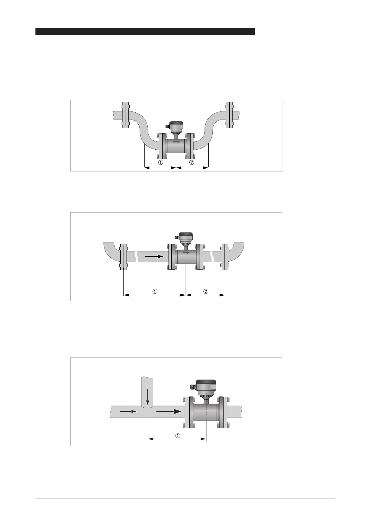
2.8 Installation conditions
2.8.1 Inlet and outlet
2.8.2 T-section
DN25...300
Figure 2-7: Minimal inlet and outlet
1 Inlet: 0 DN
2 Outlet: 0 DN
DN350...600
Figure 2-8: Minimal inlet and outlet
1 Inlet: 3 DN
2 Outlet: 1 DN
Figure 2-9: Distance behind a T-section
1 DN 25...300: 0 DN & DN 350...600: 3 DN

Questions and Answers:

Question and Answer IconNeed help?

Do you have a question about the ITRON SHARPFLOW SWB7 and is the answer not in the manual?

ITRON SHARPFLOW SWB7 Specifications

General IconGeneral
BrandITRON
ModelSHARPFLOW SWB7
CategoryMeasuring Instruments
LanguageEnglish

Related product manuals