EasyManuals Logo

ITRON SHARPFLOW SWB7 User Manual

ITRON SHARPFLOW SWB7
32 pages
To Next Page IconTo Next Page
To Previous Page IconTo Previous Page
Page #14 background imageLoading...
Page #14 background image
2 INSTALLATION
14
SHARPFLOW SWB7 + CWB7
www.itron.com WA-0092.0-EN-qs-06.13
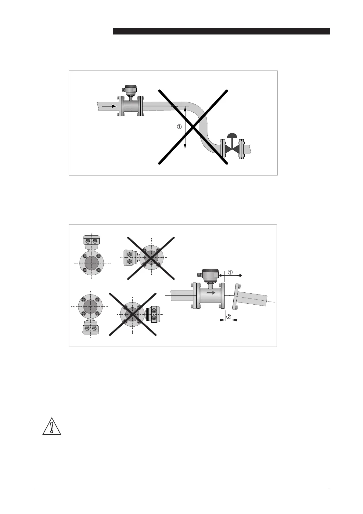
2.8.8 Mounting position and flange deviation
Mount flow sensor either with signal converter aligned upwards or downwards.
Install flow sensor in line with the pipe axis.
Pipe flange faces must be parallel to each other.
Figure 2-16: Vacuum
1 5 m
Figure 2-17: Mounting position and flange deviation
1 L
max
2 L
min
CAUTION!
Max. permissible deviation of pipe flange faces: L
max
- L
min
0.5 mm / 0.02".

Questions and Answers:

Question and Answer IconNeed help?

Do you have a question about the ITRON SHARPFLOW SWB7 and is the answer not in the manual?

ITRON SHARPFLOW SWB7 Specifications

General IconGeneral
BrandITRON
ModelSHARPFLOW SWB7
CategoryMeasuring Instruments
LanguageEnglish

Related product manuals