ELECTRICAL CONNECTIONS 3
21
SHARPFLOW SWB7 + CWB7
www.itron.comWA-0092.0-EN-qs-06.13
3.3 Connection of the signal cable
3.3.1 IP 67 housing (field version)
Dimensions of cable
CAUTION!
To ensure smooth functioning, always use the signal cables included in the delivery.
INFORMATION!
The signal cable is only used for remote versions. The standard WSC-cable includes both
electrode and field current leads.
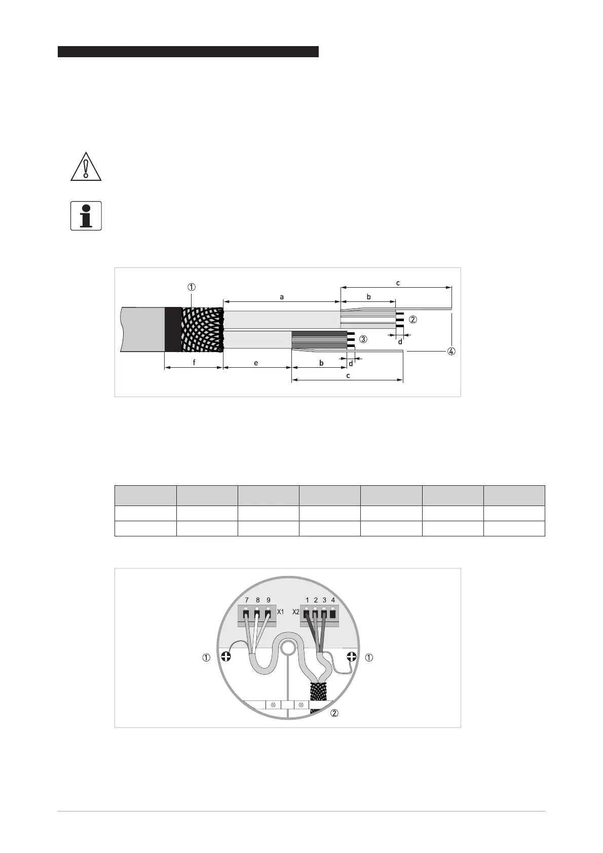
Figure 3-2: Preparation of standard cable (both sides)
1 Shielding
2 Blue + green + yellow cable, used for field current (terminals 7, 8, 9)
3 Brown + white + violet cable, used for electrode signals (terminals 1, 2, 3)
4 Drain wires
a b c d e f
mm 75 35 70 5 45 30
inch 3.0 1.4 2.8 0.2 1.8 1.2
Figure 3-3: Cable connection at sensor side, standard cable
1 Connect drain wires under screw
2 Connect shielding under clamp