3 ELECTRICAL CONNECTIONS
22
SHARPFLOW SWB7 + CWB7
www.itron.com WA-0092.0-EN-qs-06.13
• Prepare appropriate cable lengths as shown.
• Connect the wires as shown in the following table.
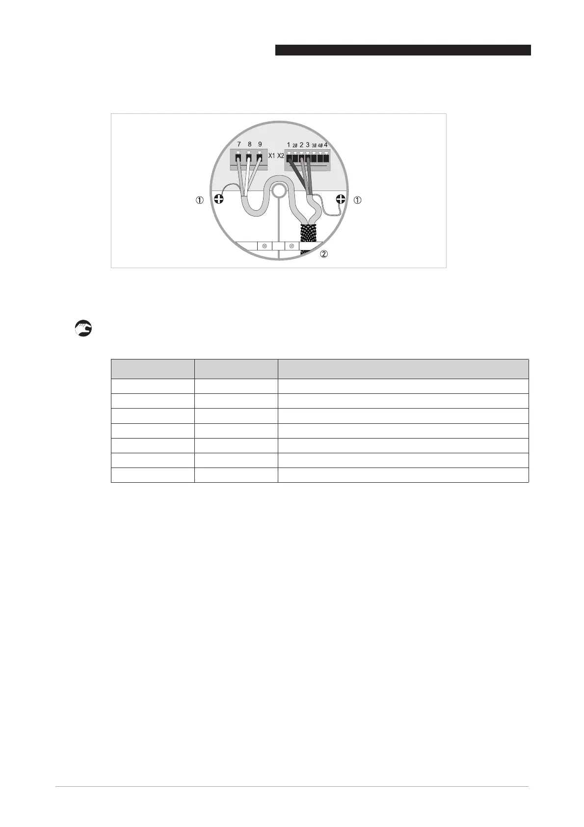
Figure 3-4: Cable connection at converter side, standard cable
1 Connect drain wires under screw
2 Connect shielding under clamp
Wire color Terminal Function
Brown 1 Reference electrode
White 2 Standard electrode signal
Violet 3 Standard electrode signal
Blue 7 Field current
Green 8 Field current
Yellow 9 No function
Drain wires Screws Shielding