Pancode VoIP/Pantel VoIP Access Control Door Phones
Installation and Programming Manual
Figure 4-6 BNC female socket connector
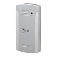
The analog video stream can be routed directly to a TV Monitor
1. Customer takes the full responsibility on the video camera functionality in case when
the third part external video camera will be used with the door units. The
manufacturer’s supplied video camera’s technical parameters shown in the Paragraph
(See Paragraph
7.1)
Figure 4-7 Video Camera Connections
For the internal video camera installation:
• Install the Video Camera to the “Internal video camera installation place”
• Connect the Video Camera’s electrical power wires to the appropriate PCB Main connector’s pins
11 – 12 (See Figure 4-5 and Figure 4-8)
• Connect the video output BNC-F connector to the Video Monitor
• Connect all the rest required door unit’s connections (LAN, Door lock, Exit button etc.)
• Connect the supplied Pancode / Pantel external ~12 VAC power supply and switch on the unit
• Configure and adjust the video monitor follow by the Video Monitor configuration instructions in
order to get the video image from the video camera.
15