Pancode VoIP/Pantel VoIP Access Control Door Phones
Installation and Programming Manual
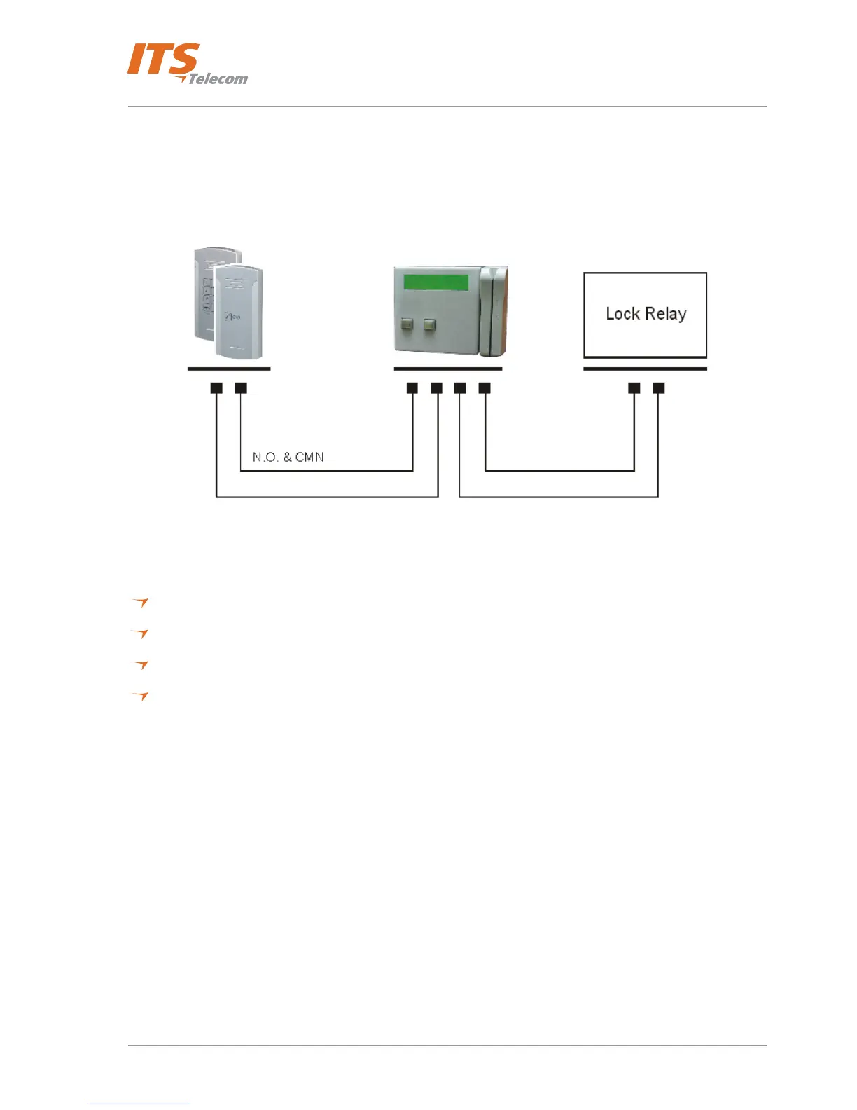
To add a Pantel VoIP/Pancode VoIP to an access control device:
The access control device opens the door when the Pantel/Pancode triggers the access-control device.
For this installation, the access-control device “Bypass Switch” (SW) wires are connected to the “N.O.” and
“CMN” terminals of the Pantel/Pancode. The door-lock relay wires are connected to the access-control device
(see Figure
4-25).
Figure 4-25. Access Control – Controlling Lock Relay
Connection schematics:
The Pantel VoIP and Pancode VoIP offer multiple wiring options:
Option 1: For use with an external device, which requires the unit to be set up as “Normally Closed”.
Option 2: For use with an external device, which requires the unit to be set up as “Normally Open”.
Option 3: For use with the powered-unlocked-state lock relay (most common).
Option 4: For use with the powered-locked-state lock relay (recommended for safety purposes).
28