EasyManua.ls Logo

JAC PICOMATIC 450 - 12 List of Components in Illustrations

JAC PICOMATIC 450
151 pages
Print Icon
To Next Page IconTo Next Page
To Previous Page IconTo Previous Page
Loading...
English
21
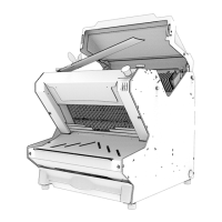
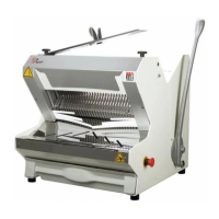
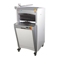
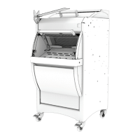
12 LIST OF COMPONENTS IN ILLUSTRATIONS
Figure
Item
Description
1
Rear cover
1
2
Bagger
3
Loaf pusher
4
Cover
5
Emergency stop button
6
Loaf holder
7
Front table
8
Crumb tray
9
Wheeled base (optional)
10
Braked castors
11
Rear cover safety switch
12
Thumbscrew
13
Rear table
14
Rear panel
15
Power cable
2
16
Photoelectric cell light curtain (optional)
17
Indicator lamp or illuminated button
18
Digital display (MRK – MRF – MRL ETL)
19
Photoelectric cell (optional)
20
Rear cover
3
21
Work area
4
22
Wheeled base assembly screw
23
Wheeled base silent block bushing
24
Wheeled base retaining nut
6
25
Digital screen
26
Display power on (MRK – MRF – MRL ETL)
27
Programming key (MRK – MRF – MRL ETL) (for use by a
technician only)
28
Display power off (MRK – MRF – MRL ETL)
29
Oil top-up reset (MRF)
7
30
Isolator switch
9
31
“Moving parts hazard” sign
32
“Cut hazard” sign
33
Circuit diagram
34
“Electrocution hazard” sign
10
35
Detachable loaf holder spring
36
Bagger adjustable stop

Table of Contents

Related product manuals