REMOTE SENSOR INSTALLATION
40
Use a separate 18-2 shielded cable for sensor wiring. Prior to wiring the sensor
to the thermostat, use an ohm-meter or multi-meter to measure the resistance of
the sensor. Measure at the end of the wires that will connect to the thermostat.
Confirm the resistance value (within 5%) to the temperature where the sensor is
mounted. Refer to the Temperature/Resistance Chart on page 41 of this manual.
Use a high quality, digital electronic thermometer to read the temperature at the
sensor. Remove the sensor cover and place the thermometer probe next to the
thermistor to verify an accurate reading. Disconnect power to the thermostat
when wiring the sensor to the proper sensor terminals. Strip only as much
insulation off of the wires as necessary to provide a good contact with the
terminals. The sensor is not polarity specific so either sensor lead may be
connected to either designated terminal on the thermostat. Refer to the T-32-RS2
installation guide for additional information.
T-32-OTS OUTDOOR SENSOR INSTALLATION
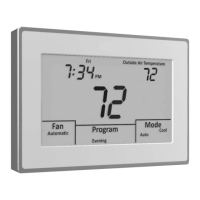
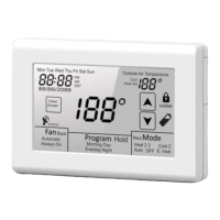
When the T-32-OTS is wired to the T-32-TS, it will display the outside air
temperature as well as control high and low balance points for heat pump or dual
fuel systems. Refer to the T-32-OTS installation guide for additional information.
 Loading...