TABLE DIMENSIONS
CORNER INSTALLATION
TABLE DIMENSIONS
CONNECTION TO DISHMACHINE
TABLE DIMENSIONS STRAIGHT
THROUGH INSTALLATION
C
OPENING
D
E
A
B
A
C
OPENING
D
C
G
F (ROLL)
A
B
D
C
OPENING
D
LETTER DIM (IN) DIM (CM)
A 4” (MIN) 10.2 CM (MIN)
B 2 1/2” 6.4 CM
C 20 1/2” 52.1 CM
D 25 1/4” 64.1 CM
E 2 1/4” 10.2 CM
F 1 1/2” 3.8 CM
G 3/4” 1.9 CM
9
INSTALLATION INSTRUCTIONS
INSTALLATION & OPERATION
Jackson WWS Inc. provides technical support for all of the dishmachines detailed in this manual and recommends that
service personnel have this manual on hand when calling technical support staff. Technical support is available from 8:00
a.m. to 5:00 p.m. (EST), Monday through Friday. Technical support is not available on holidays. Contact technical support
toll free at 1-888-800-5672. Please remember that technical support is available for service personnel only.
VISUAL INSPECTION: Before installing unit check container and machine for damage. A damaged container may be an
indication of damage to the machine. If there is any type of damage to both container and unit, do not throw away the
container. The dishmachine has been inspected at the factory prior to shipping and is expected to arrive in new, undamaged
condition. However, rough handling by carriers or others may result in damage to the unit while it is in transit. If such a
situation occurs, do not return the unit to the manufacturer. Instead, contact the carrier and ask them to send a representative
to the site to inspect the damage, and request that an inspection report be completed.
Contact the carrier within 48 hours of receiving the machine (to report possible freight damage) and the dealer from whom
the unit was purchased.
UNPACKING THE DISHMACHINE: The machine should be unboxed and removed from the pallet prior to installing. Open
the front door and remove all of the materials from the inside. Once unpacked, verify there are no missing parts. If a part
is missing, contact manufacturer immediately.
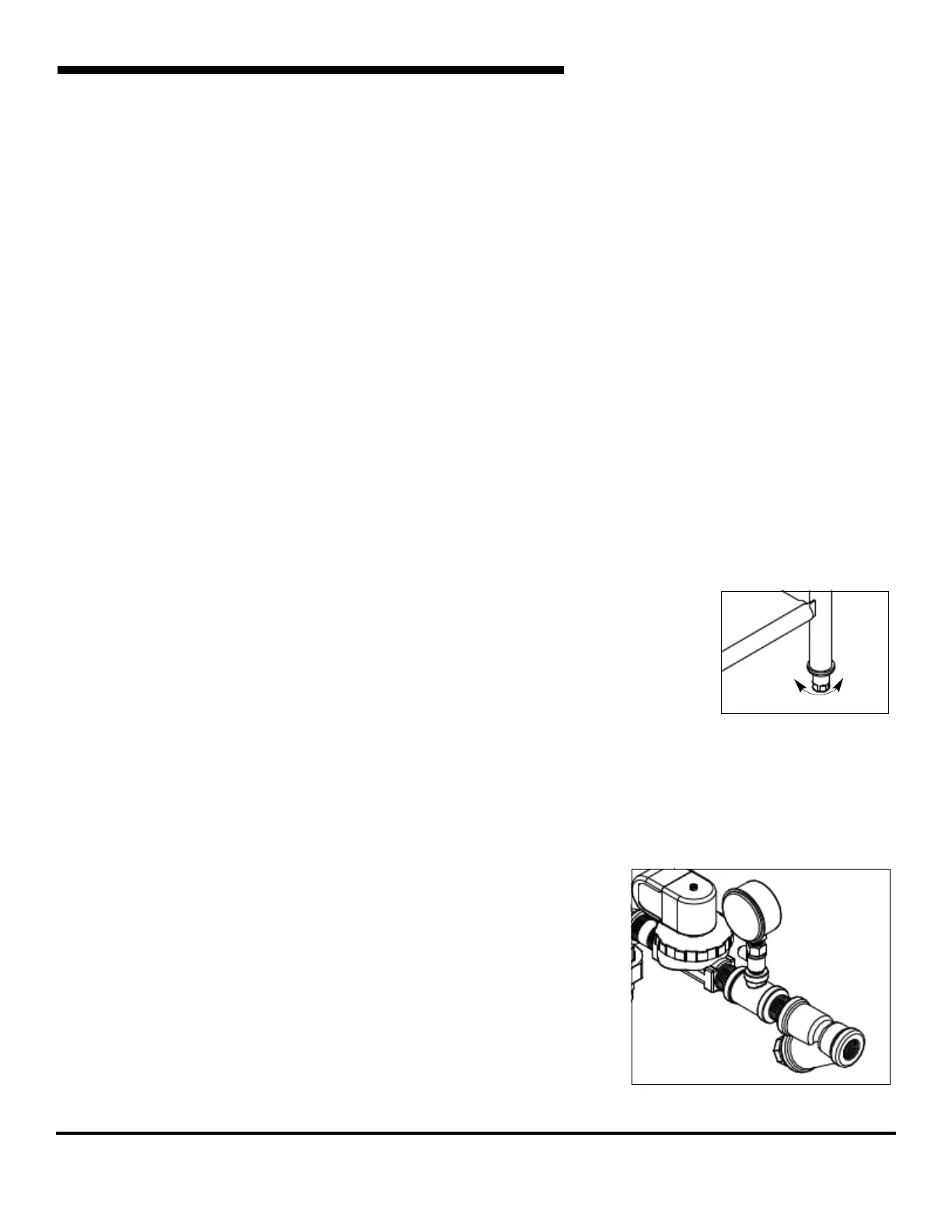
LEVEL THE DISHMACHINE: The dishmachine is designed to operate while level. This is
important to prevent any damage to the machine during operation and to ensure the best
results possible. The unit comes equipped with adjustable bullet feet which can be turned
using a pair of pliers. Verify the unit is level from front to back and side to side before making
any electrical or plumbing connections.
PLUMBING THE DISHMACHINE: All plumbing connections must be made to adhere to local,
state, territorial and national codes. The installing plumber is responsible for ensuring the in-
coming water lines are ushed of debris prior to connecting to the machine. Note that chips and
materials from cutting processes can become lodged in the solenoid valves and prevent them from opening or closing. Any
valves that are found to be fouled or defective because of foreign matter left in the water line, and any subsequent water
damage, are not the responsibility of the manufacturer.
A water hardness test must be performed to determine if the HTS-11 (scale prevention & corrosion control) needs to be
installed. A hardness test kit can be found on the warning tag that is attached to
the incoming plumbing connection on
the back of the machine. If water hardness is higher than 5 GPG, the HTS-11 will
need to be installed. Please contact manufacturer to purchase the HTS-11.
CONNECTING THE DRAIN LINE: The dishmachine's drain is a gravity discharge
drain. All piping from the 1 1/2” FNPT connection on the wash tank must be pitched
(1/4” per foot) to the oor or sink drain. All piping from the machine to the drain must
be a minimum 1 1/2” I.P.S. and shall not be reduced. There must also be an air
gap between the machine drain line and the oor sink or drain. If a grease trap is
required by code, it should have a ow capacity of 5 gallons per minute.
Incoming Plumbing Y-strainer Connection
Frame with Adjustable Foot
Raise
Lower
 Loading...