File Version: 1.3 / JAKA MiniCab Hardware User Manual
6 Electrical Characteristics
6.1
This chapter mainly introduces the absolute maximum ratings and recommended usage conditions of MiniCab.
It is imperative for users to adhere to the recommended electrical parameters when using the robot
and MiniCab. Exceeding the maximum ratings may result in hardware damage.
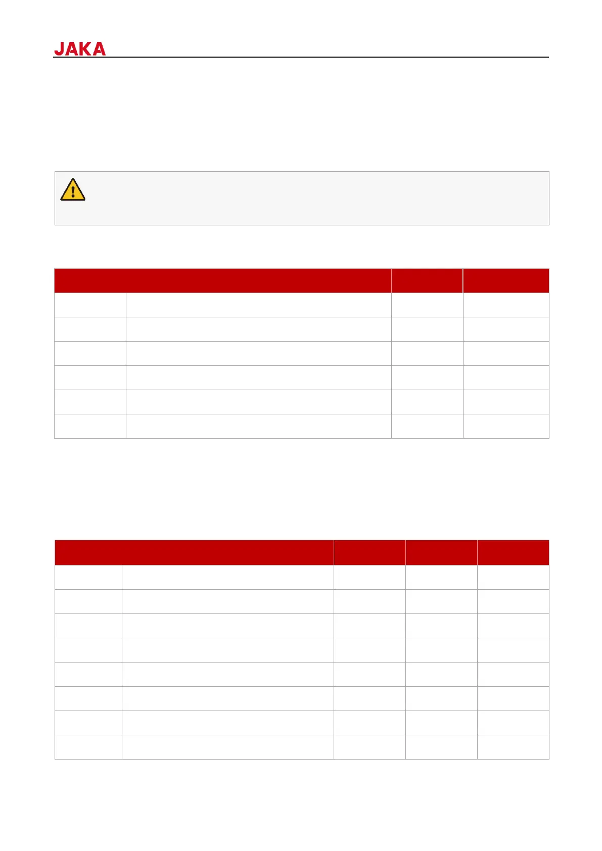
6.2
Control cabinet power voltage (V)
Integration interface common terminal voltage (V)
Integration interface output current (A)
Integration interface single channel output current (A)
RS485 bus withstand voltage (V)
ii
i: When the actual value exceeds the maximum value, it may cause permanent damage to the equipment. The
maximum value represents the limit, and it is not recommended to use the equipment under this condition or
any other condition exceeds the recommended conditions.
ii: Except the bus withstand voltage, all voltage values are related to grounding.
6.3
Control cabinet power voltage (V DC)
Robot power voltage (V DC)
Average operating current (A)
I/O interface single channel output current (A)
Ambient temperature (°C/°F)
Atmospheric pressure (Bar)
 Loading...