For update steps, please refer to the software user manual. Contact JAKA technician to obtain the update
installation package.
To ensure the safety function of the robot, the digital I/O interfaces I/O_1, I/O_2, I/O_3, I/O_4, I/O_6, and I/O_7
in the control cabinet can be configured as dedicated safety I/O. Among them, I/O_6 and I/O_7 can only be
configured as safety DI, and can only be configured for protective stop function. The other four channels can be
configured as safety DI or safety DO. The electrical specifications of the safety I/O interfaces are the same as
the digital I/O interfaces The safety I/O is designed with dual redundancy, so if one channel fails, the safety
function still works. Therefore, when wiring, a pair of safety I/O should be connected simultaneously. For
example, when connecting I/O_1, I/O_2 must be connected at the same time. The pairing relationship of the
safety I/O is as follows:
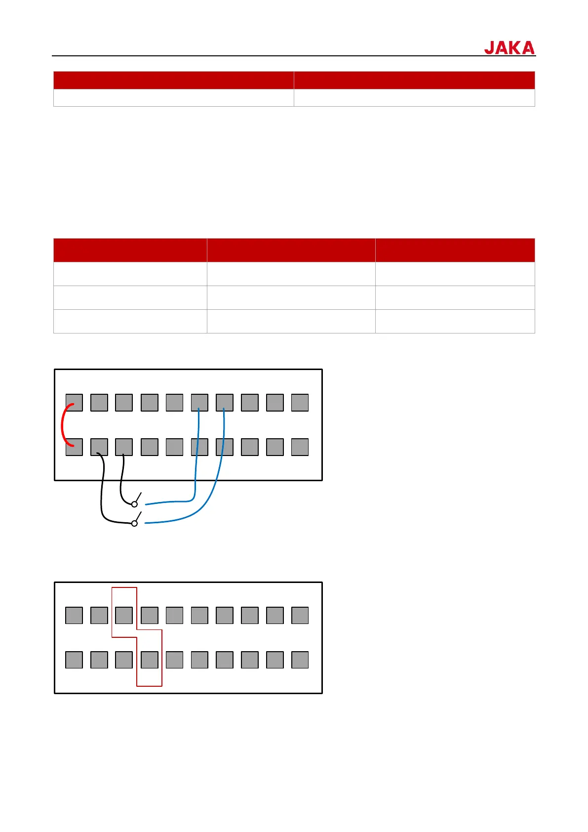
Taking the DI1 & DI2 as an example, the wiring diagram is as follows (When using internal UDIO_24V, please
short PIN1 and PIN2):
7.1.1.3
MiniCab can be powered on after power is supplied for 4 seconds. Besides using the power on/off button on the
control stick and the POWER button on the front panel of the control cabinet, MiniCab can also be remotely
powered on and off by PIN5 and PIN8 of the I/O interface on the front panel of the control cabinet.
When using an external power on/off button, a self-resetting/momentary push button switch must be used,
 Loading...