File Version: 1.3 / JAKA MiniCab Hardware User Manual
7.1.5
The STICK interface is used to connect the control stick. Simply insert the control stick connection cable into
this interface to connect. This interface is only for connecting the JAKA control stick and should not be modified.
7.1.6
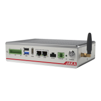
The control cabinet provides safety function input interfaces, which the emergency stop function is valid by
configuring the interface. This interface is designed with dual redundancy, and the function can be activated
when either signal is valid. If external safety equipment is required, select devices that with dual redundancy.
Users can connect safety doors, safety light curtains, and sensors according to requirements.
The external emergency stop input interface is double row 3.5 mm (0.14 in) pitch pluggable terminal blocks, and
the interface definition is as follows.
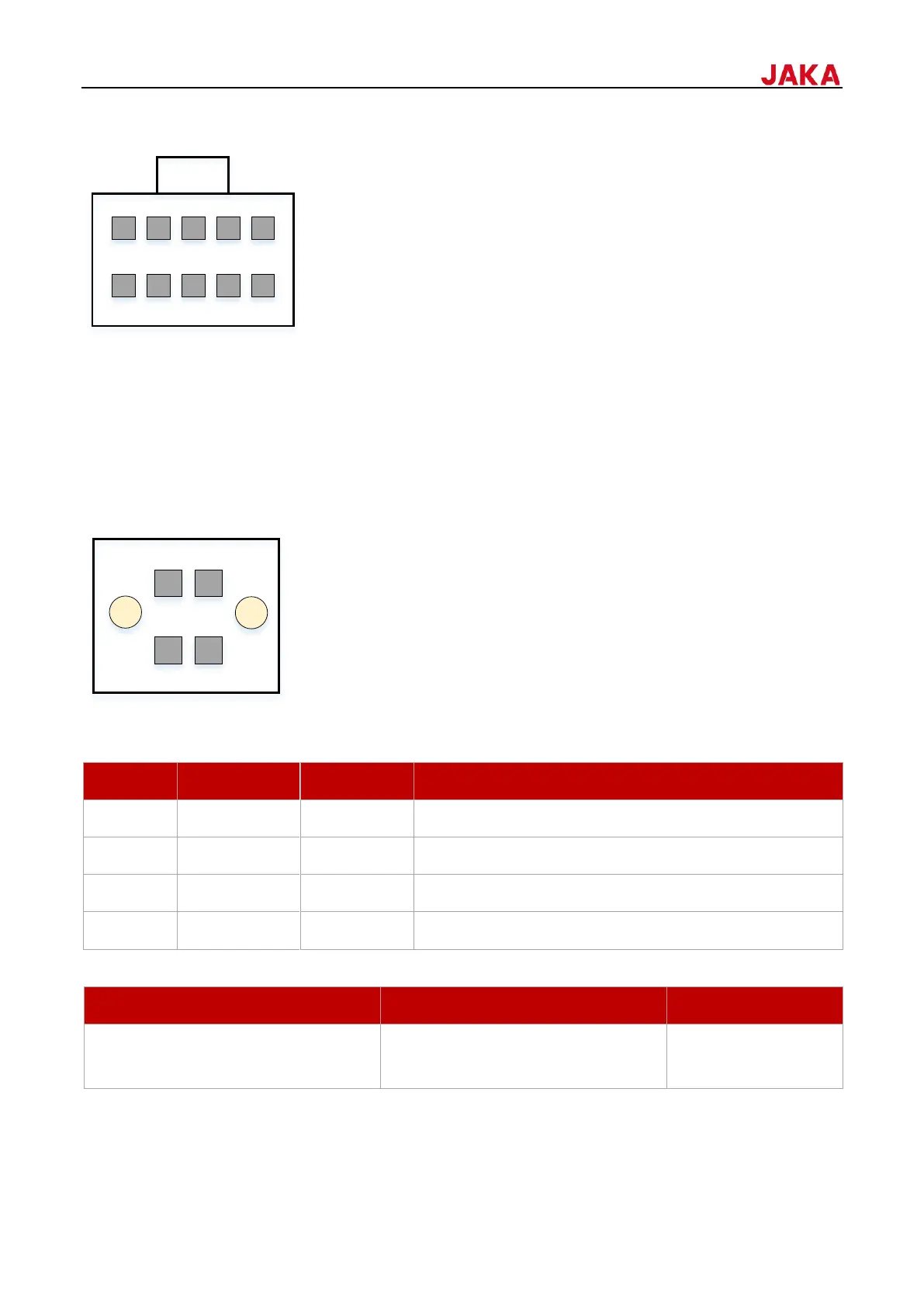
7.1.6.1
When not connected to an external emergency stop device, pins 1 & 2 and pins 3 & 4 should be shorted. By
default, they are shorted to the internal 24V. The wiring diagram is as follows.