File Version: 1.3 / JAKA MiniCab Hardware User Manual
1.
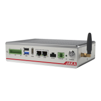
When configured as DI, it is an NPN type input, and IO_1 (PIN13) is valid when shorted to GND (PIN6). When
using internal UDIO_24V, please short PIN1 and PIN2. Taking DI_1 as an example, the wiring diagram for other
DI interfaces is the same. The wiring diagram is as follows:
K1
1 3 5 7 9
2 4 6 8
10
11 13 15 17 19
12 14 16 18 20
2.
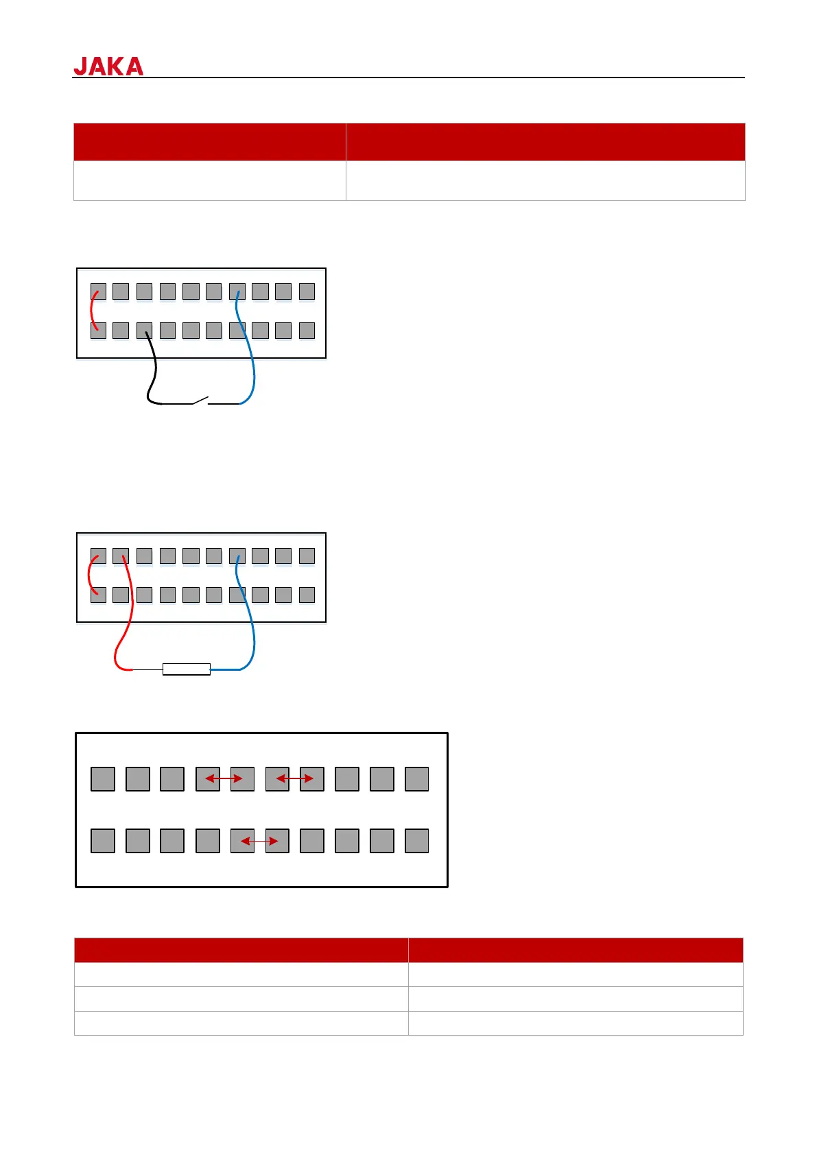
When configured as DO, it is an NPN type output, which uses an open collector output internally and is
connected with a freewheeling diode. It supports a maximum output current of 1A. When using internal
UDIO_24V, please short PIN1 and PIN2. Taking DO_1 as an example, the wiring diagram for other DO interfaces
is the same. The wiring diagram is as follows:
1 3 5 7 9
2 4 6 8
10
11 13 15 17 19
12 14 16 18 20
LOAD
7.1.1.2
The safety I/O function is only supported in software versions 1.7.1.37 and above. Therefore, before using the
safety I/O function, an upgrade is required. The version requirements are as follows:
1 3 5 7 9 11 13 15 17 19
2 4 6 8 10 12 14 16 18 20