File Version: 1.3 / JAKA MiniCab Hardware User Manual
The robot power input (PIN2) supplies power to the robot and can also supply power to the control cabinet.
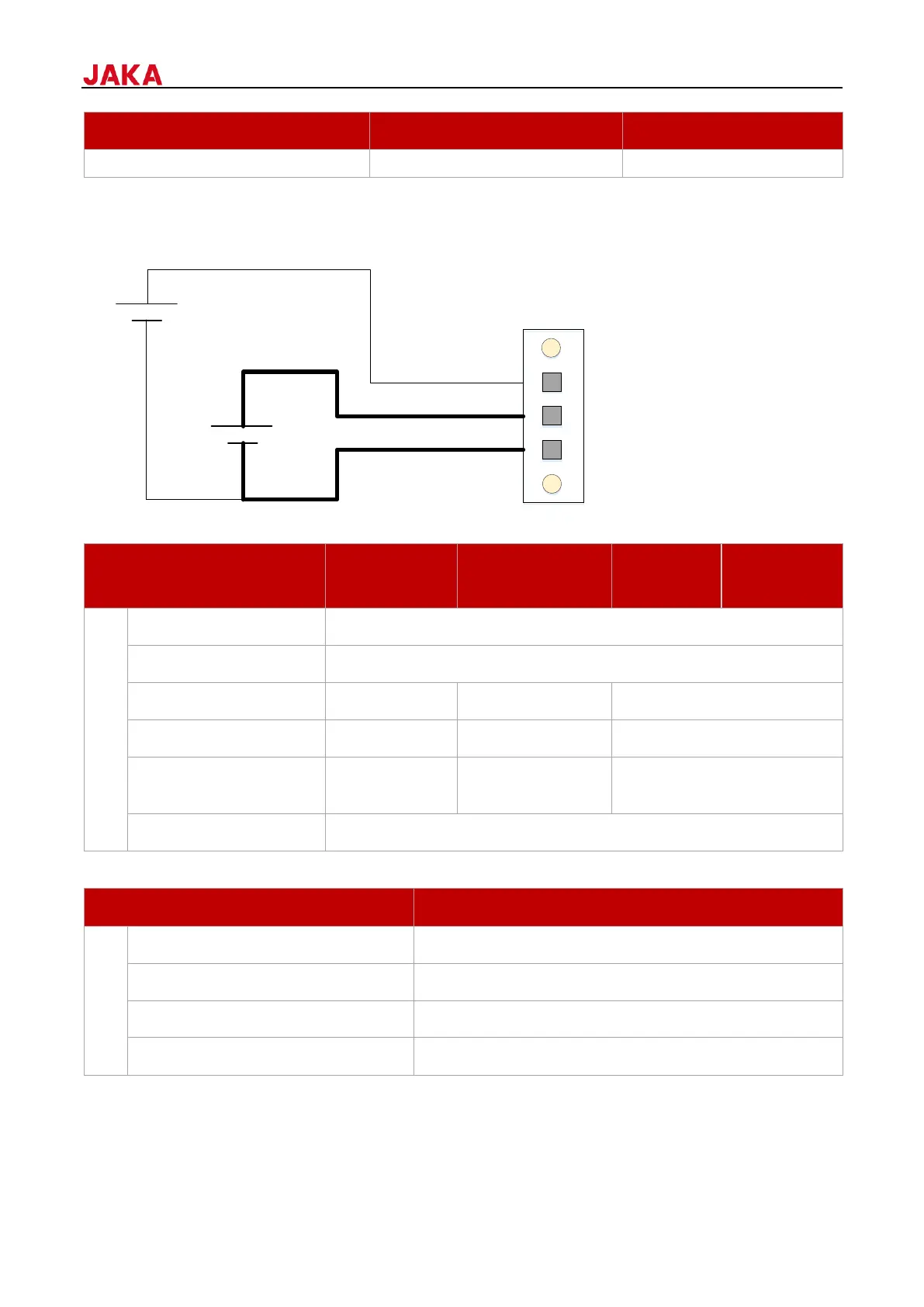
When control cabinet power and robot power do not need to be separated, connect PIN2 and PIN3. If you need
to disconnect VP+ in emergency situations while keeping the control cabinet powered, you can separately
connect the power supply to VL+. The wiring diagram is as follows.
1. The robot power supply requirements are as follows.
RSP-1000-48*2 or
RSP-2000-48*1
RSP-1000-48*3 or RSP-3000-
48*1
2. The control cabinet power supply requirements are as follows.
Typical power consumption
Note:
i: 30V is not included; the robot under voltage threshold is 30V.
ii: The power supply models listed here are only for recommendation, you can purchase power supplies of
equivalent specifications. Additionally, peak power consumption is dependent on the robot's load and usage
scenario. The values listed here are the maximum value.
 Loading...