12
Operating Instructions
5. Attach the hydraulic lines to the tractor. Two hydraulic lines (green band) operate the inside gate mechanism. Connect these lines
to one service outlet on the tractor. Two hydraulic lines (yellow band) operate the folding mechanism of the auger. Connect these
lines to a second service outlet on the tractor. The remaining two hydraulic lines (red band) operate the hydraulic ow control spout
located at the end of the upper auger. Connect these lines to a third service outlet on the tractor. Make sure the air is bled from the
hydraulic cylinders and hoses.
6. Run the auger system EMPTY before loading grain into the tank for actual use. Make certain that the upper and lower augers are
properly engaged.
7. Connect the lighting 7-prong connector end on the main wiring harness to the tractor electrical outlet. Make sure that all asher
and turn indicator lights are working properly before incidental highway travel.
CAUTION
• Do NOT operate the grain cart before reading and understanding this Operator’s Manual and ALL danger, warning and caution signs.
• Be sure that a Slow-Moving-Vehicle emblem is attached to the rear of the grain cart.
• Never exceed 1,000 rpm on the PTO and driveline system.
• Never fold or extend the auger until the PTO has come to a complete stop.
• Never ll the grain cart unless the gate indicator is in the closed position.
• Never allow foreign objects (shovels, etc.) to be placed inside the grain cart.
• Never engage the lugs and drive dogs on the augers when the system is moving at a high rate of speed.
• Never perform maintenance work or service the grain cart with the tractor running.
1. Make sure the tractor is o and the PTO is
disengaged.
2. Disconnect the driveline from the tractor.
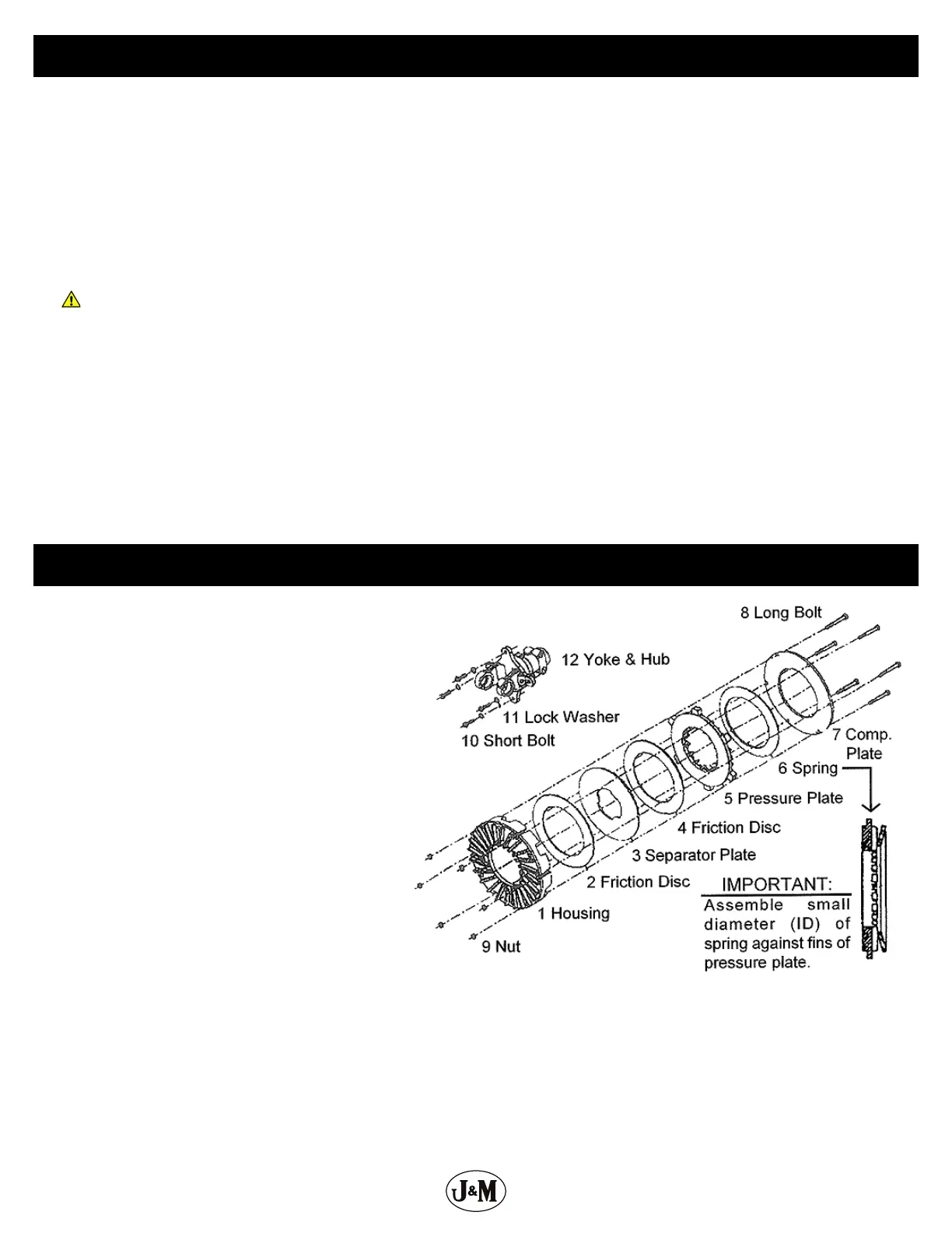
3. Locate the six (6) long bolts (item 8 in diagram) on
the O.D. of the clutch pack. Loosen the bolts until
they rotate freely, nger tighten each bolt, and then
tighten each bolt one half turn.
4. Attach the implement to the tractor with a hitch
pin and the drive line to the tractor PTO shaft.
5. Start the tractor. Engage the PTO and run a few
seconds, or until the friction clutch visibly smokes.
6. Disengage the tractor PTO and shut the tractor o.
7. Disconnect the driveline from the tractor.
8. Tighten the six (6) long bolts (item 8 in diagram) on
the O.D. of the clutch pack until the compression
plate (item 7 in diagram) is in contact with the
housing (item 1 in diagram), then keep tightening
each bolt to 30 ft.-lbs.
9. Locate the four (4) short bolts (item 10 in diagram)
that attach the yoke & hub (item 12 in diagram)
to the clutch pack and check that each bolt is
tightened to 30 ft.-lbs.
Adjusting the Slip Clutch