15
Adjusting the Lower and Upper Flighting
WARNING
MAKE SURE THAT ALL POWER IS SHUT OFF BEFORE ADJUSTING THE FLIGHTING ASSEMBLY.
LOWER FLIGHTING - If the drive-dog and hanger assembly are becoming excessively hot during unloading, the lower ighting and/or
hanger may need adjusting. The hanger bushing assembly has elongated holes where it attaches to the outer tube assembly. Loosen
the two 1/2” bolts on the hanger bushing assembly. Adjust the hanger either up or down and vertically center it between the ighting
and drive dog. Re-tighten the bolts. Make certain that the ighting center and drive-dogs do not rub the hanger bushing assembly,
causing them to become hot.
If the hanger can no longer be adjusted by moving it up or down on the elongated holes, both the hanger bushing assembly and the
lower ighting will have to be removed. After removing them from the tube assembly, place a shim [between 1/8” (0,32cm) to 3/16”
(0,48cm) thick] next to the gearbox and the spline coupler (welded to the lower ighting). Replace the lower ighting and reattach the
hanger to the tube assembly. Readjust the hanger assembly. NOTE: The bottom of the lower ighting is not attached to the gearbox
with any bolts or set screws but may be ‘frozen’ fast. Be careful when removing the lower ighting from the gearbox. For easier removal
of the lower ighting, keep the gearbox at the bottom intact, remove the two 1/2” bolts from the hanger bushing assembly and pull the
lower ighting o of the gearbox.
After adjusting the lower ighting, move the upper auger to the unload position and check the upper ighting for readjustment.
UPPER FLIGHTING - If the upper and lower augers to do not properly separate during the unfolding sequence, the upper ighting
may need adjusting. Before making adjustment to the upper ighting, check to see if the lugs and drive dogs on the auger assemblies
are locking together. If they are not locked together, check to see if a faulty check valve on the hydraulic cylinder used to raise and lower
the upper auger assembly may be causing the problem.
Fold the upper tube assembly into the upright position. Position the upper ighting in the engaged position with the lower ighting.
Locate the four-hole ange bearing on the top of the upper auger tube housing. With the upper ighting in the engaged position,
check the spacing between the upper bearing and the upper tube housing. There must be an 1/8” (0,32cm) space between the base of
the four-hole ange bearing and the upper tube housing. If there is NOT a space between the bearing and the upper tube housing, or
if there is more than 1/8” (0,32cm) space, the upper ighting will need to be adjusted. To adjust the upper ighting, loosen the 1-1/4”
hex nuts both above and below the four-hole ange bearing. Move the 1-1/4” hex nuts up or down the threaded shaft on the top of the
auger ighting shaft until the bearing moves to approximately 1/8” (0,32cm) above the base of the upper tube housing. When the four-
hole ange bearing is properly located, tighten both 1-1/4” hex nuts together to secure the bearing position.
If the upper and lower ighting still do not separate properly during the folding sequence, a small bevel may need to be removed from
the inside of the lugs where they engage the drive dogs on the auger assemblies. Grind approximately 1/8” (0,32cm) from the corner of
the lugs where they touch against the drive dogs.
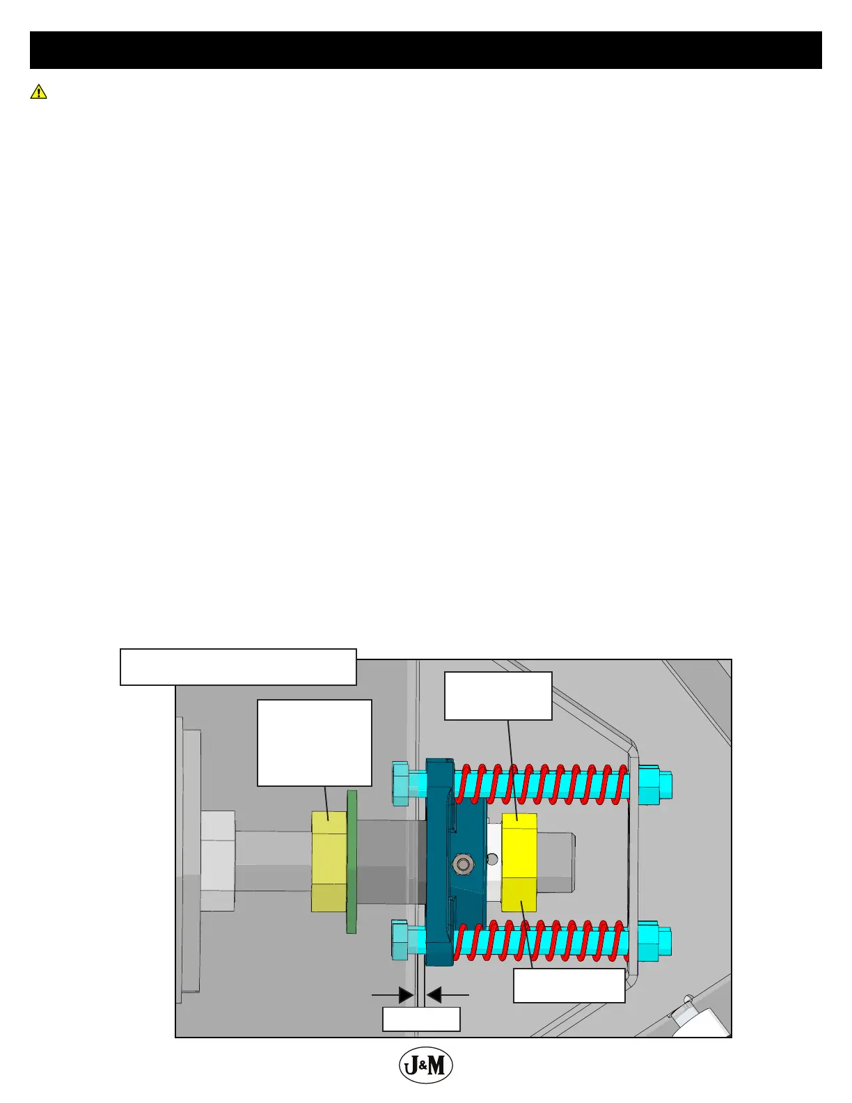
1. Untighten the
1-1/4” hex nut at
least 1/4”.
2. Tighten the 1-1/4”
hex nut until there is
a 1/8” to 3/16” gap
between the 4 hole
ange bearing and
the headpan.
1/8”-3/16”
3.
Tighten the 1-1/4”
hex nut back up.
Adjusting Upper Auger