Page 17
ENGLISH
Jandy
®
Pro Series, JXi
™
Gas-Fired Pool & Spa Heater
|
Installation & Operation Manual
Any conguration other than as illustrated in Figure 12
can affect the operation of the water pressure switch.
Locating the heater above or below the pool water surface
can also affect operation of the switch.
NOTE: When pool equipment is located below the pool
surface, Zodiac Pool Systems, Inc. is not responsible
for any large scale water loss, flooding or damage
caused by a leak.
The heater must be protected from back-siphoning of
water, which can result in dry starts. If there is any chance
of back-siphoning, provide a check valve between the
pool and the lter pump inlet.
5.2 Pump Sizing
The internal ow bypass within the heater manifold
will accommodate ows delivered to the heater from a
minimum of 30 gallons per minute (gpm) to a maximum
ow of 120 gpm, depending on the heater model. A
manual bypass valve should be installed when the pump
ow exceeds 120 gpm.
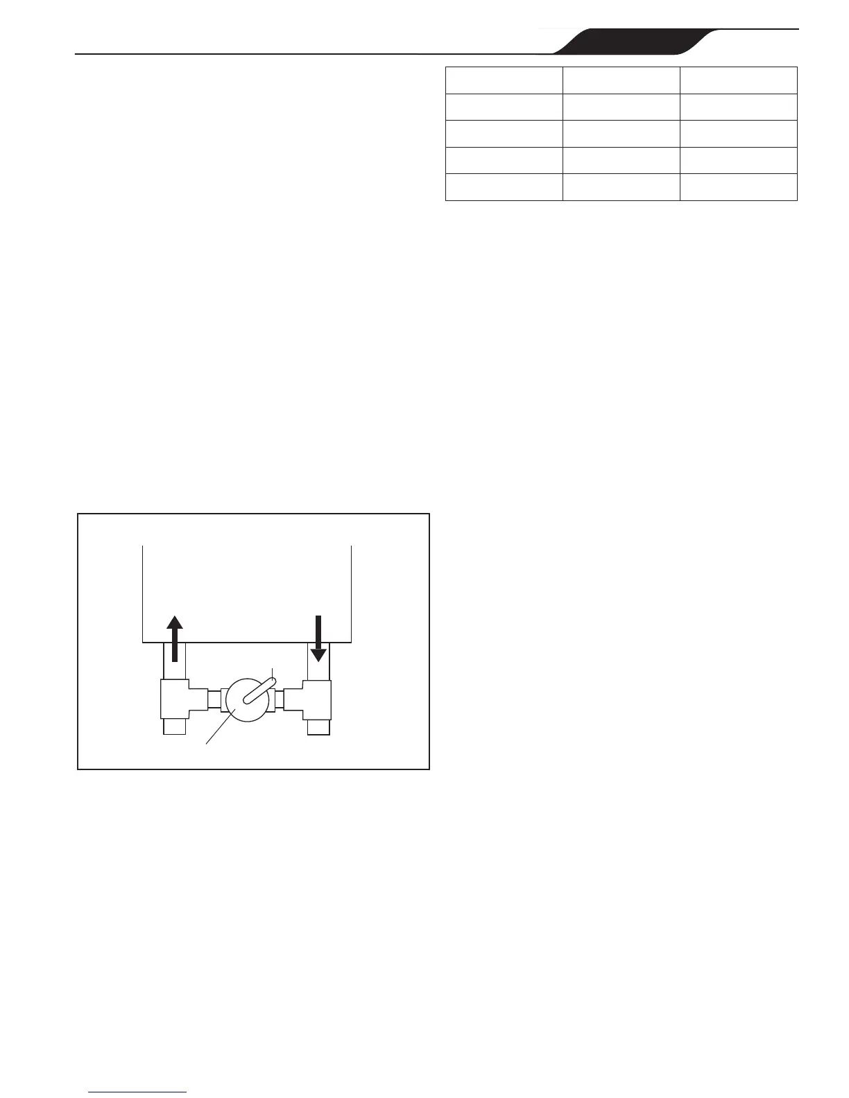
To install a manual bypass valve:
1. Connect ball valve valve between water inlet and
outlet (Figure 13).
Figure 13. Install Manual Bypass Valve
Heater
IN OUT
Ball Valve
Handle
IMPORTANT
The system water pump must be capable of providing
no less than 30 gpm of flow through the heater.
Flow rates at less than 30 gpm may cause nuisance
operation causing the heater to turn off or damage to
the heater.
2. Adjust the valve to bring the ow rate within the
acceptable range (see Table 6).
Model Min gpm (lpm) Max gpm (lpm)
200 30 (114) 120 (454)
260 30 (114) 120 (454)
330 30 (114) 120 (454)
400 30 (114) 120 (454)
Table 6. Recommended Flow Rate Adjustment
3. Remove the valve handle to avoid tampering.
Pump Sizing for New Pool Construction:
When sizing a pump for the system, the head loss for
all system components must be added together when
determining the design ow rate. Component “Head
Loss at Flow” curves are available from equipment
manufacturers.
NOTE: In order to properly establish head loss at flow for a
filter, remember that a “dirty” filter can typically add 10
psi of additional head loss (23 extra feet of head). This
must be considered when sizing a pump for a new
pool system.
Pump Sizing for Replacement in an Existing Pool:
If the JXi heater replaces a different model of heater,
determine if the existing pump is capable of providing the
minimum ow of no less than 30 gpm indicated in Table
6 for the specic model. JXi heaters are high efciency
heaters. Heaters typical of this construction may have
higher head loss characteristics than the one being
replaced.
IMPORTANT
Heater failure due to insufficient water flow is not
covered under warranty. See measurements in the
Head Loss Chart, Figure 14.