Page 12
ENGLISH
Jandy
®
Pro Series, JXi
™
Gas-Fired Pool & Spa Heater
|
Installation & Operation Manual
Apply RTV at seal after connecting.
Use minimum 600°F (315°C)
temperature rated RTV.
Figure 8. Seal Connection with RTV
3.3.2 Vertical Venting (Category I)
All indoor installations and outdoor shelter installations
require an approved 4 inch double-wall appliance adapter
and increaser to be connected to the JXi 4-inch ue collar
for Type B installations. Increasers are available in steps
up to a maximum of four sizes larger. 4 inch double-
wall appliance adapters and increasers can be obtained
from manufacturers such as Amerivent or Duravent
®
(see Section 2.3 for detailed specications). All vent
installations must be made in accordance with local, state,
or provincial codes and with:
• National Fuel Gas Code ANSI
®
Z223.1 (NFPA
®
54),
latest edition; pay particular attention to the chapter
addressing “Venting of Equipment.” Applicable
provisions of additional applicable local building
codes may also need to be followed.
• Canada CAN/CSA B149.1.
Vent the JXi heater vertically in a negative pressure (non-
positive draft) system in accordance with the National
Fuel Gas Code NFPA 54 / ANSI Z223.1 or the Canadian
Natural Gas and Propane Installation Code, CAN/
CSA-B149.1. A type B double-wall vent connector is
required. The heater must not be used to support the vent
pipe.
Note that the tables for fan-assisted appliances include
both maximum and minimum vent loading gures in the
NFPFA 54. The primary purpose of the maximum ratings
are to ensure that the vent operates with negative pressure
throughout its length. The minimum rating refers to the
ring rate.
1. Determine the correct vent size for your heater
according to Table 2.
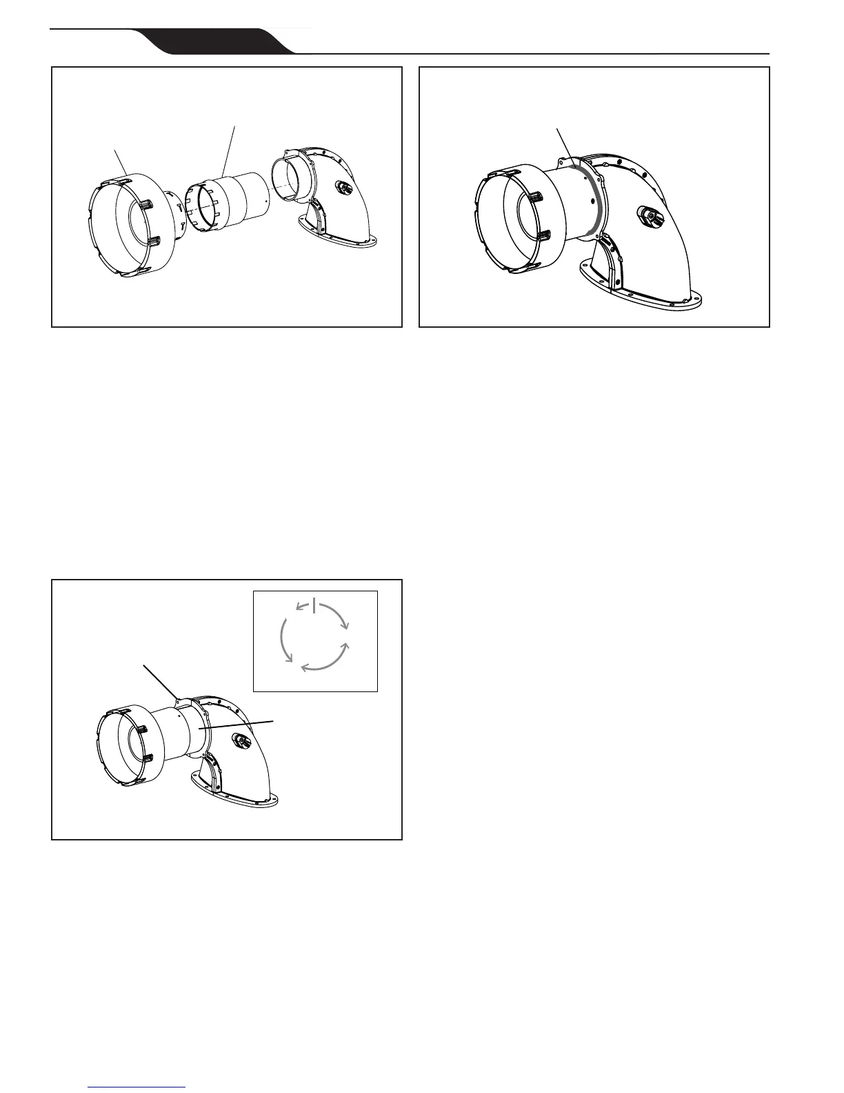
Increaser
4 inch double-wall
appliance adapter
Figure6. CategoryIInstallationConguration
4. Wipe the socket of the vent body with rubbing
alcohol using a clean cloth or paper towel, then.
dry with a different clean cloth.
5. Connect the 4 inch double-wall appliance adapter
for category I or vent connector for category III to
the ue collar and fasten with three (3) sheet metal
screws, as shown in Figure 7).
NOTE: It is important to position the three screws so the seal
in the flue collar is not compromised. Begin with first
screw at 3 o’clock position from top of the flue collar
seam. Install screws 2 and 3 in positions 120 degrees
apart (as shown in Figure 7).
Figure 7. Correct positioning of screws
on vent collar
Start with
screw (1) at
3 o’clock position
Fasten three
screws, positioned
at 120° intervals
from top seam in
vent collar
screw
(3)
screw
(2)
seam
screw
(1)
120°
120°
120°
6. Apply high temperature silicone RTV at the
connection to seal, as shown in Figure 8.
NOTE: Use a minimum 600°F (315°C) temperature rated RTV.