Page 7
ENGLISH
Jandy
®
Pro Series, JXi
™
Gas-Fired Pool & Spa Heater
|
Installation & Operation Manual
6. High Limit Switches - Two (2) limit switches -
one at the heat exchanger rst pass (135°F/57°C)
and one at the heat exchanger outlet (150°F/65°C)
-- prevent water of excessive temperatures from
being discharged from the heater. If either switch
senses excessive temperature, the gas valve will
close and combustion will stop.
7. Water Pressure Switch - Operating the heater
without sufcient water ow may severely
damage the heater. This control senses whether or
not water is available to the heater by measuring
back pressure at the header inlet. If the pool
water pump fails or the water lter is blocked, the
pressure switch prevents operation of the burner.
The display will indicate a no ow fault to alert
you that water pressure is insufcient.
NOTE: If the heater is installed below the surface level of the
pool,(or more than two feet above the pool level), the
pressure switch setting must be adjusted. See section
5.4 Adjusting the Water Pressure Switch.
8. Vent Temperature Limit (240°C/464°F)- This
is a single use switch, which detects abnormal
temperatures in the vent system. It is mounted
to the exhaust duct. Excessive temperatures
will cause the switch to open. Excessive
temperatures can be caused by inadequate water
ow or a compromised heat exchanger. The vent
temperature limit switch will open the safety
circuit which shuts off the gas valve and shuts
down the heater. If this limit is activated/tripped,
the heater cannot be safely operated without rst
determining the cause and without replacing the
limit switch with an exact replacement.
9. Air Pressure Switch - The air pressure switch
monitors the vacuum (negative pressure) within
the blower housing. This switch veries that air
is owing through the combustion system by
sensing pressure. It shuts off the heater if air ow
is inadequate.
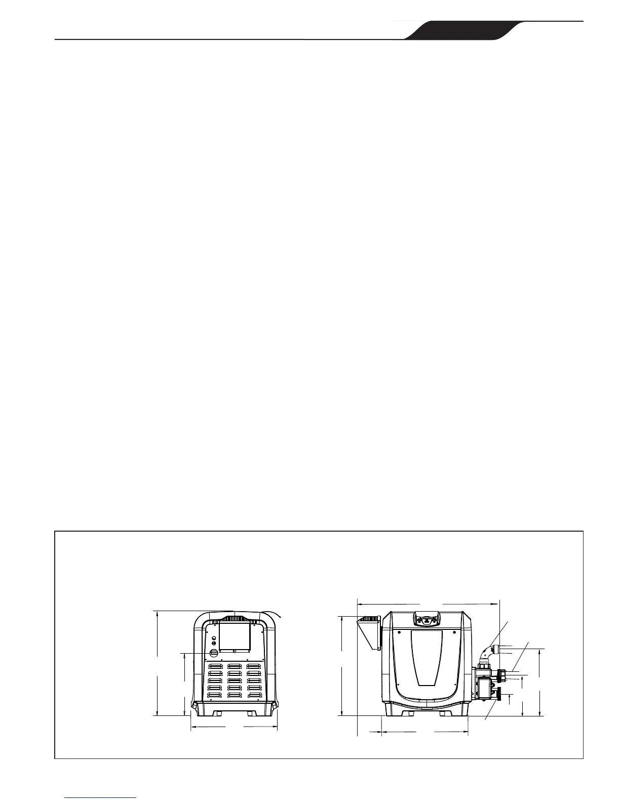
2.5 Dimensions
See Figure 1 for exterior dimensions and dimensions to
critical connections.
2.6 Clearances
In both indoor installations (US) and outdoor shelter
installations (Canada), the heater must be placed to
provide clearances on all sides for maintenance and
inspection, as well as maintain minimum distances from
combustible surfaces.
NOTE Clearances are manufacturer’s tested values. These
are given as minimum values. Where local and national codes
apply, and if the clearance values specified in the applicable
codes are different that those listed in this manual, use the
greater value to ensure safest operation.
2.6.1 Combustible Surfaces
The following minimum clearances must be maintained
from combustible surfaces during operation. See Section
2.6.2 for clearances required for service and inspection.
TOP: 6 inches (15 cm)
EXHAUST SIDE: 6 inches (15 cm) from
surface of the exhaust vent
HEADER SIDE: 6 inches (15 cm)
DOOR PANELS: 6 inches (15 cm)
The dimensions shown in Figure 1 are certied by CSA
for USA and Canada (outdoor shelter). In Canada, 24
inches (60 cm) clearance is required per CSA B149.1,
section 4.14.2.
Figure1. GeneralConguration
26.5"
(67 cm)
21.0
25.2"
(64 cm)
18.5"
22.1"
(56 cm)
36.5"
(93 cm)
22.9"
10.13"
5.6"
Outlet
*Optional Inlet
*VersaPlumb
®
Sweep Elbow Inlet
6.3"
EXHAUST SIDE
FRONT
(16 cm) (58 cm)
(14.2 cm)
(25.7cm)
(47 cm)
*Union nut, cap, and O-ring
provided for unused inlet. Sweep
16.0"
(40.6 cm)