Page 11
3.3 Installing the Power Pack and Cell
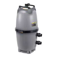
7. Invert the lower clamp and place on the pipe. Mark the pipe for drilling the feeder holes (see Figure 7).
8. Drill the feeder holes using the holesaw provided. Ensure holes are clean and smooth (see Figure 8).
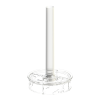
9. Usethepipespacerasshownifmountingona1½in.(40mm)pipe(seeFigure9).
NOTE:Thepipespacerisrequiredfor1½in.(40mm)diameterpipeonly.Thespacerisnotrequiredon
2in.(50mm)pipe.
Figure 8. Drilling Feeder Holes Figure 9. Pipe Spacer
Figure 4. Installation
Requirements
Figure 7. Marking Pipe for
Drilling Feeder Holes
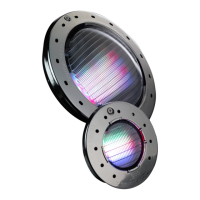
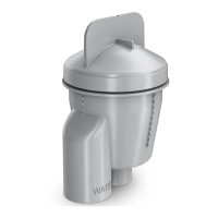
Figure 5. Attaching the Power Pack
Screws
Thru-holes
Feeder Holes
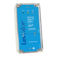
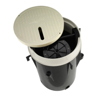
Figure 6. Disassemble Cell
Lower
Clamp
Upper
Clamp
Push-button
15 ft (4.6 m) MAX
Spacer used for 1 ½ in
(40mm) pipe only
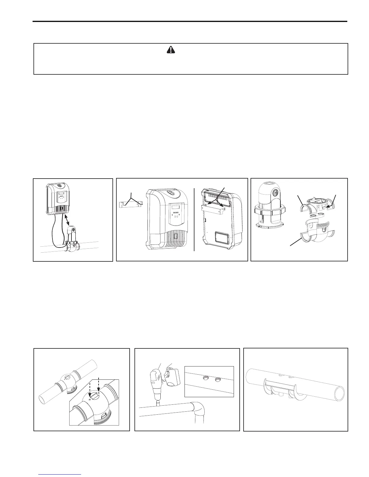
1. Ensure placement of the cell and the power pack will meet all the installation requirements outlined in Section 3.2.
2. Screwthepowerpackbracketintopositionensuringitisnomorethan15ft.(4.6m)fromthecell
(seeFigure4and5).
3. Position the power pack in place by aligning the bracket with the corresponding thru-holes (see Figure 5).
4. Wirethepowerpacktoapowersourceand,ifavailable,anAquaLink®RSControlSystemorPDA
(seeSections3.4-3.6).
5. Unscrewthelockingringfromthecellinordertoextractitfromtheupperclamp(seeFigure6).
6. Pressthetwo(2)push-buttonsoneithersideoftheupperclamptoseparatetheupperclampfromthelowerclamp
(seeFigure6).
WARNING
Toavoidpropertydamage,seriousinjuryordeath,donotoperatetheelectrolyticcellwithoutwatercirculation.Abuildupof
ammablegasseswhichcanresultinFIREOREXPLOSION.