Page 12
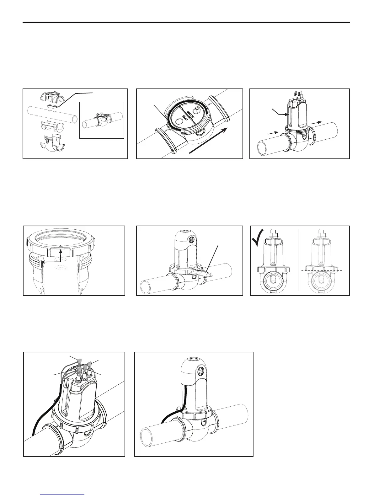
Figure 11. Water Flow Arrows
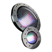
Figure 13. Locking Ring
Alignment
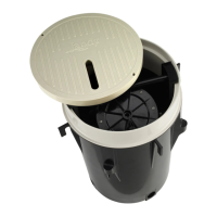
Figure 17. Attaching Terminal Cap
Figure 14. Locking Ring
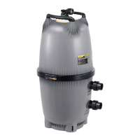
Figure 16. Connecting Cell Leads
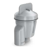
Figure 12. Cell Attached
Figure 15. Locking Ring Level
10. Verify the gasket is attached to the upper clamp. The curved side of the gasket must be pointing down so that it
will create a seal with the pipe.
11. Securetheclamps,pipespacer,andgasketaroundthepipeasshown(seeFigure10)makingsuretheowarrows
ontheclamppointinthedirectionofthewaterow(seeFigure11).Makesurethetwo(2)clipsonthesidesof
the clamp are snapped into place.
12.
Insert the o-ring into the channel on the clamp
and then attach the cell (see Figure 11 and 12).
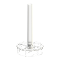
13. Position the locking ring in proper alignment, making sure the bump aligns with the top thread (see Figure 13).
14. Screwdownthelockingringtothethreadedclampusingthelockingringtool(seeFigure14).
NOTE: Ensurethelockingringislevelwhenengagingthethreadingclamp(seeFigure15).
15 Securelyconnectthecellleadstothelikecoloredterminals(seeFigure16).
16. Attachtheterminalcap(seeFigure17).
Figure 10. Attaching Cell Clamps
Gasket
(Attachestotheupperclamp)
Red
Red
Blue
Black
x
Locking Ring
Tool
Water Flow
O-Ring
Inlet
Outlet
The groove
must be on
the inlet side
Align the bump with
the high thread on
the lower clamp.
NOTE: The Upper
Clamp is not shown
in this diagram but it
should be installed.