Page 9
Jandy
Heat Pump Models EE-Ti Installation and Maintenance Manual
Section 3. Water Connections
3.1 Plumbing Layout
Figure 4 illustrates the standard plumbing layout
with a single heat pump unit. Following the diagram
from right to left, the plumbing sequence is as follows:
Pool > Pool Pump > Filter > Heat Pump > Check
Valve > Chemical Loop > Chlorinator > Pool
NOTE For normal installations, do not install a shutoff
valve or any kind of variable restriction in the
water piping between the heat pump outlet and
the pool/spa.
Arrangement of pool system components other
than as illustrated in the preceding and following
diagrams can affect the operation of the heat pump’s
water pressure switch. Location of the heat pump
above or below the pool water surface can also affect
operation of the switch. In general, the pressure switch
can be adjusted to accommodate this effect if the heat
pump water connections are no more than 5 feet below
the pool water surface or no more than 11 feet above it.
See instructions for pressure switch adjustment (Section
5.6) in the heat pump start-up section of this manual for
more information. If the heat pump is installed outside
of this range, an external flow switch may need to be
installed in the plumbing upstream of the heat pump.
Call the Zodiac technical support department at (800)
822-7933 for details.
Be advised that when pool equipment is located
below the pool surface a leak can result in large scale
water loss or flooding. Zodiac cannot be responsible for
such water loss or flooding or the damage caused by
either occurrence.
3.2 Water Connections at Heat Pump
Shipping plugs have been installed in the water
inlet and outlet ports of the heat pump at the factory.
Before installing any plumbing, remove the shipping
plugs. Filtered water is plumbed to the inlet, located on
the right side of the heat pump front panel. Heated water
flows through the outlet, located on the left side of the
heat pump front. Two inch unions are provided.
Plastic piping (PVC Schedule 40) should be
connected to the heat pump. The unions, provided with
the unit, accept 2” PVC pipe.
CAUTION
Make sure that fl ow requirements and pool
water turn over rates can be maintained with
the installation of additional heat pumps and
plumbing restrictions.
ATTENTION
Assurez-vous que la circulation d’eau requise
soit maintenue même si des pompes d’appoints
ou des éléments de plomberie, causant des
restrictions, sont ajoutés.
PRECAUCIÓN
Asegúrese de que los requerimientos de fl ujo
e índices de volumen de agua de la piscina
puedan mantenerse, con la instalación de
bombas de calentar adicionales y restricciones
de fontanería.
3.3 Check Valve Installation
The heat pump must be protected from back-
siphoning of water. If there is any chance of back-
siphoning, provide a check valve between the pool and
the filter pump inlet.
Figure 3. Anchor Clamp Installation
3" minimum
1/4" x 1-1/2"
STAINLESS STEEL
TAPCON
®
TYPE
CONCRETE SCREW
AND WASHER
(Installer Provided)
EVAPORATOR
COIL GUARD
EVAPORATOR
COIL
HEAT PUMP
PLASTIC BASE
HEAT PUMP
ANCHOR
BRACKET
3/16" DRILLED
HOLE
CONCRETE
EQUIPMENT PAD
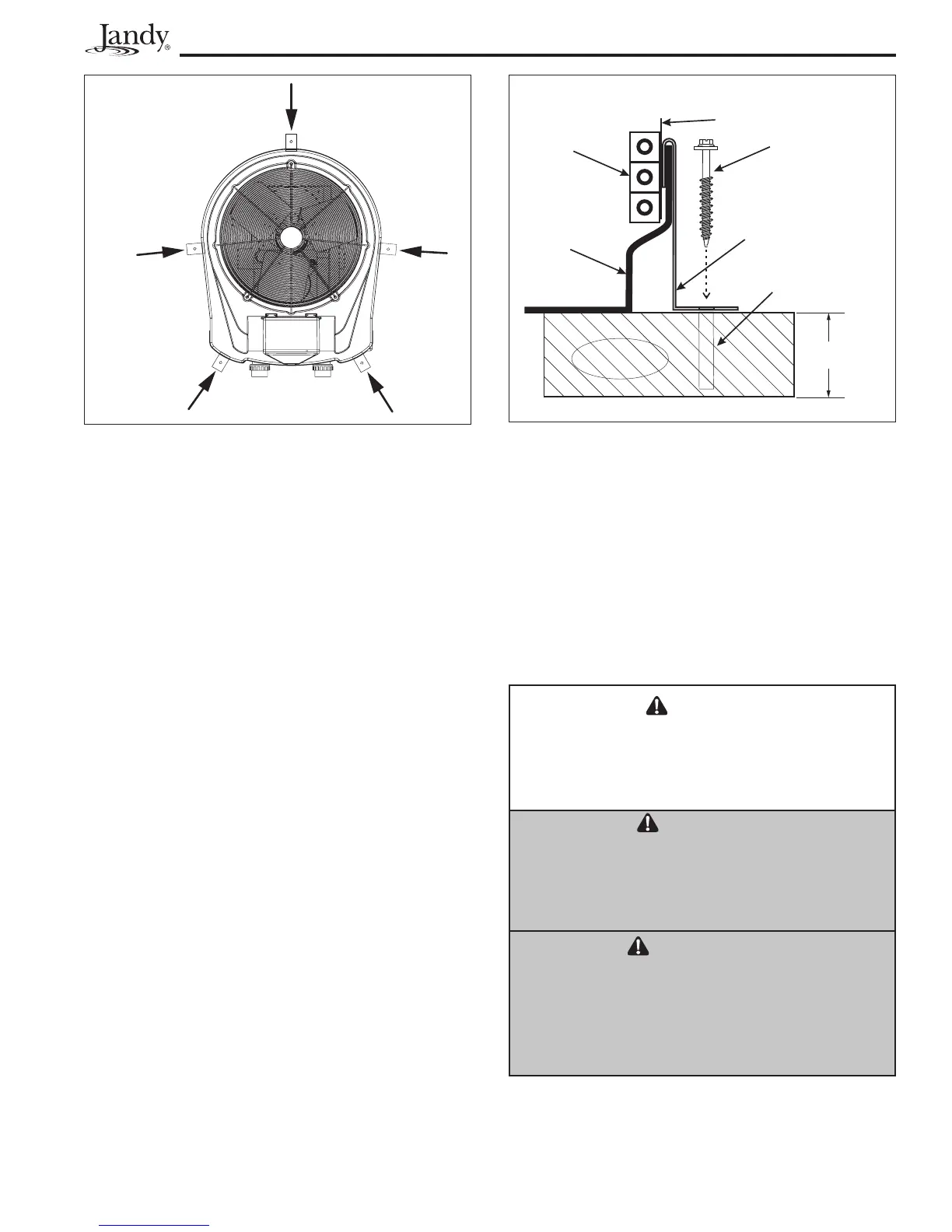
Attach anchor
brackets to base
of heat pump
where indicated
by the arrows.
Figure 2. Anchor Clamp Positions