Page 17
Jandy
Heat Pump Models EE-Ti Installation and Maintenance Manual
Relay is needed. See Figure 10.
4.5 Optional Remote Controls
Electrical wiring must be in accordance with all
applicable national and local codes and ordinances.
4.5.1 Connection to a Remote Pool-Off-
Spa Selector (3-Wire Connection)
4.5.1.1 Install the Remote Pool-Off-Spa
Selector
1. Turn off the power to both the pool/spa control
system and the heat pump unit.
2. Remove the screws that attach the service/access
panel to the heat pump unit and the cover to the
junction box (see Figure 11).
3. Run the wires from the pool/spa control system
into the conduit connection labeled “Low Voltage
Connection”, located on the lower right hand side
of the heat pump (see Figure 11).
4. Connect the wiring from the pool/spa control
system to the heat pump remote control terminal
(see Figure 12a).
5. Restore power to the heat pump and the pool/spa
control system.
4.5.1.2 Confi gure the Control Panel
1. Make sure the control is in the OFF mode.
2. To enter the Service Setup mode, press and hold
the MENU, POOL, and SPA buttons for 5
seconds.
NOTE The display will revert back to OFF after one
minute since the last key press.
3. Press the Up or Down button to display
REMOTE. Press the MENU button. The
SELECT REMOTE OFF (default remote)
appears, use the Up or Down button to scroll
through the Remote options. When you reach HI-
LO-COM, press the MENU button to select the
remote. Press POOL or SPA to exit the Service
Setup mode.
4.5.2 Two-Wire Connection to an
AquaLink
®
RS or TSTAT
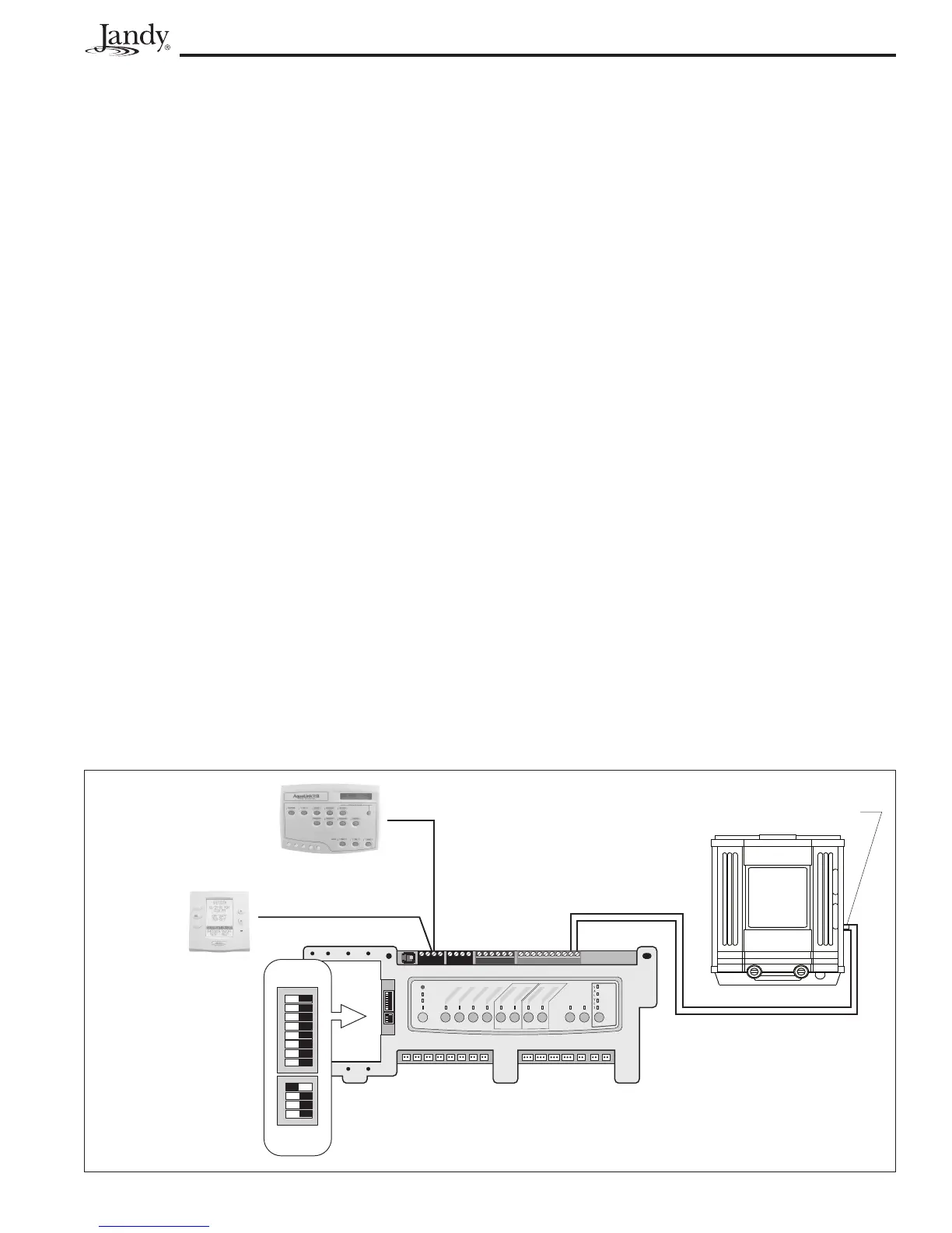
4.5.2.1 Confi gure the AquaLink RS Control
System
1. Turn off the power to both the pool/spa control
system and the heat pump unit.
2. Connect two (2) wires to the AquaLink RS green
10-pin terminals 1 and 2.
3. Put DIP S2-1 (pin #1 of the 4 position DIP switch)
into the ON position (see Figure 13).
4.5.2.2 Install the Remote TSTAT
1. Turn off the power to both the pool/spa control
system and the heat pump unit.
2. Remove the screws that attach the service/access
panel to the heat pump unit and the cover to the
junction box (See Figure 11).
3. Run the wires from the pool/spa control system
into the conduit connection labeled “low voltage
connection”, located on the lower right hand side
of the heat pump (See Figure 11).
Figure 13. AquaLink RS to EE-Ti Heat Pump
Heat Pump
Green - Enabled
Red - On
Heat Pump Connections
Terminals 1 and 2
LED
will not
come on
for Heat
Pump
Connector for Low
Voltage Wires
DIP Switches
S1 and S2
S1
S2
RESET
SERVICE
TIME OUT
FILTER PUMP
A
UX 1
AUX 2
AUX 3
A
UX 4
AUX 5
A
UX 6
A
UX
7
RS6 & RS8 ONLY
RS8 ONLY
HEATER
SOLAR
POOL MODE
SPA MODE
SPA DRAIN
SPA FILL
AUTO
654321
10987654321
4321
4321
S1
S2
OFF ON
OFF ON
1 2 3 4 5 6 7 8
1 2 3 4