EasyManua.ls Logo

Jandy JE - Installation of Anchor Clamps

Jandy JE
96 pages
To Next Page IconTo Next Page
To Previous Page IconTo Previous Page
Loading...
Page 7
ENGLISH
Jandy
®
Pro Series JE Heat Pumps
|
Installation and Operation Manual
 
3.5"
8"
B
A
C
F
E
D
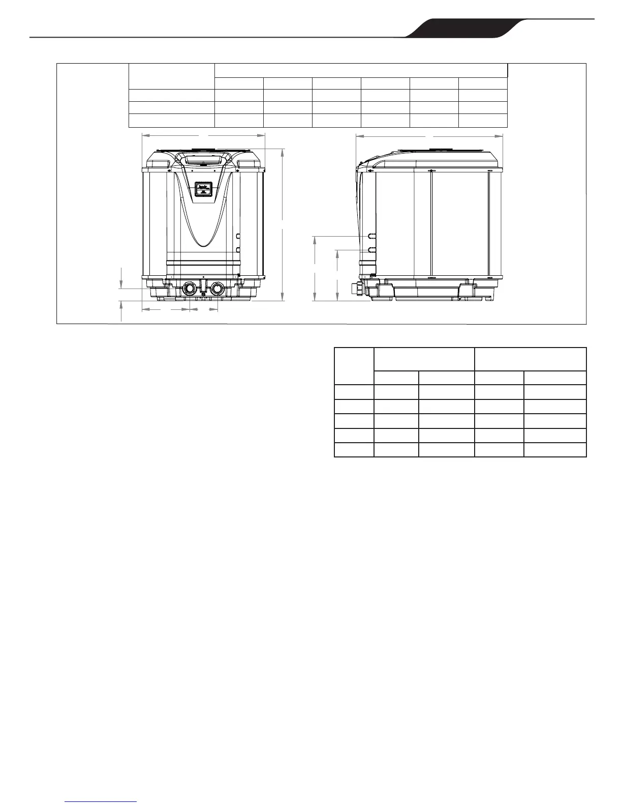
MODEL SIZE DIMENSIONS
A B C D E F
JE1500T 33” 34” 12.5” 9” 7” 39”
JE2000/2500T 36” 40” 13.8” 19” 15” 43”
JE3000T 36” 44” 13.8” 19” 15” 43”












 Ensure that the pad is pitched not more than ¼
inch per foot cm per toward the compressor end
(front) of the heat pump. Pitch slab from back to
front ¼ inch per foot maximum and level from
side to side.














Side of
Heat
pump
Minimum Clearances for
Operation
Recommended Clearances
for Serviceability
Inches Centimeters Inches Centimeters
Front 24 60 36 90
Rear 12 30 24 60
Left 12 30 24 60
Right 12 30 24 60
Top 60 150 60 150
 Clearances listed in Table 2 are manufacturer’s tested values.
These are given as minimum values. Where local and national codes
apply, and values are different than those listed in Table 2, use the
greater value to ensure safe and proper operation.






















Table of Contents

Related product manuals