Page 14
ENGLISH
Jandy
®
Pro Series VS FloPro™ Series Variable-Speed Pump
|
Installation & Operation Manual
3.4 Auxiliary Load Operation (for VS-
FHP2.0)
The VS-FHP2.0 is equipped with a terminal bar that
provides user access to a built-in Auxiliary Load relay
contact. This normally-open, dry contact is activated
under certain operating conditions and is primarily
intended to be used to control external devices that
require system water ow for proper functioning, such as
heaters, booster pumps, salt water chlorinators, etc.
See Figures 9 and 10 for compartment’s location details.
An access cover with Phillips-head screw must be
removed before proceeding.
Auxiliary Load Connection Requirements
WARNING
ELECTRICAL SHOCK HAZARD
Due to the potential risk of fire, electric shock,
or injuries to persons, Zodiac® Pumps must be
installed in accordance with the National Electrical
Code
®
(NEC
®
), all local electrical and safety codes,
and the occupational Safety and Health Act (OSHA).
Copies of the NEC may be ordered from the National
Protection Association, 470 Atlantic Ave., Boston,
MA 02210, or from your local government inspection
agency.
In Canada, Zodiac Pumps must be installed in
accordance with the Canadian Electrical Code
(CEC).
Note: The Auxiliary Load relay contacts are rated at
230V/11A RMS. Please ensure the requirements of the
equipment to be connected to the Auxiliary Load do not
exceed this rating.
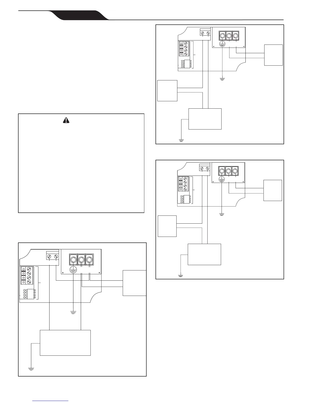
F1015 F1014
TP133
TP130
TP127
/100
For
Controller
1 2
230V
Auxiliary
Load
230V
Power
Source
L2 L1
L1
(Black)
L2
(Red or
Black)
Earth
L2
(Red or Black)
Earth
Note: In this configuration, it is important to verify the shared
power source is adequately rated to service both the pump
and the auxiliary equipment.
Figure 12. 230V Auxiliary Load, Shared Power
Source Wiring Diagram
F1015 F1014
TP133
TP130
TP127
/100
For
Controller
1 2
115V
Auxiliary
Load
230V
Power
Source
L2 L1
L1
(Black)
L2
(Red or
Black)
Earth
Earth
115V
Power
Source
Line
(Black)
Line
(Black)
Neutral
(White)
Figure 13. 115V Auxiliary Load, Separate Power
Sources Wiring Diagram
F1015 F1014
TP133
TP130
TP127
/100
For
Controller
1 2
230V
Auxiliary
Load
230V
Power
Source
L2 L1
L1
(Black)
L2
(Red or
Black)
Earth
Earth
230V
Power
Source
Line
(Black)
L1
(Black)
L2
(Red or Black)
Figure 14. 230V Auxiliary Load, Separate Power
Sources Wiring Diagram
Auxiliary Load Operation Characteristics
Auxiliary Load relay contact activation is speed-
dependent, and behaves as follows:
Contact Closure
From a stopped condition, there is a three-minute delay
before the Auxiliary Load contact is closed when the
motor speed reaches and maintains a speed of at least
1725 RPM.
From a running condition at below 1725 RPM, there is
a ve-second delay before the Auxiliary Load contact
is closed when the motor speed reaches and maintains a
speed of at least 1725 RPM.
 Loading...