Page 9
ENGLISH
Jandy
®
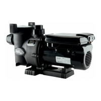
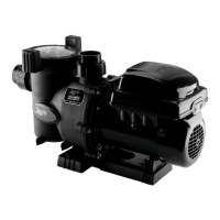
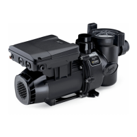
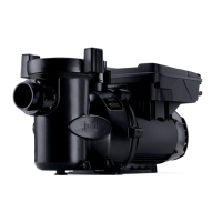
Pro Series VS FloPro™ Series Variable-Speed Pump
|
Installation & Operation Manual
It is the responsibility of the electrical installer to provide
data plate operating voltage to the pump by ensuring
proper circuit sizes and wire sizes for this specic
application.
The National Electrical Code
®
(NEC
®
, NFPA-70)
requires all pool pump circuits be protected with a
Ground Fault Interrupter (GFCI). Therefore, it is also
the responsibility of the electrical installer to ensure that
the pump circuit is in compliance with this and all other
applicable requirements of the National Electrical Code
(NEC) and any other applicable installation codes.
CAUTION
Failure to provide data plate voltage (within 10%)
during operation will cause the motor to overheat and
void the warranty.
Bonding and Grounding
1. In addition to being properly grounded as described
in Electrical Wiring section, and in accordance with
the requirements of the National Electrical Code
(NEC), or in Canada the Canadian Electrical Code
(CEC), the pump motor must be bonded to all metal
parts of the swimming pool, spa or hot tub structure
and to all electrical components and equipment
associated with the pool/spa water circulation
system.
2. The bonding must be accomplished by using a solid
copper conductor, No. 8 AWG or larger. In Canada
No. 6 AWG or larger must be used. Bond the motor
using the external bonding lug provided on the
motor frame.
WARNING
Always disconnect the power source before working
on a motor or its connected load.
WARNING
Make sure that the control switch, time clock, or
control system is installed in an accessible location,
so that in the event of an equipment failure or a loose
plumbing fitting, the equipment can be turned off.
This location must not be in the same area as the
pool pump, filter, and other equipment.
CAUTION
The pump must be permanently connected to a
dedicated electrical circuit. No other equipment,
lights, appliances, or outlets may be connected to the
pump circuit, with the exception of devices that may
be required to operate simultaneously with the pump,
such as a chlorinating device or heater.
Table 2. VS FloPro Dimensions
Base Configuration
Suction
Side
Height
Pump
Height
1. Pump without Base 7 3/4”
(197 mm)
12 3/4”
(44 mm)
2. Pump with Base 9"
(229 mm)
14"
(356 mm)
3. Pump with Base and
Spacers
9 1/4”
235 mm)
14 1/4”
(362 mm)
4. Pump with Small + Large
Base
10 7/8”
276 mm)
15 7/8”
(403 mm)
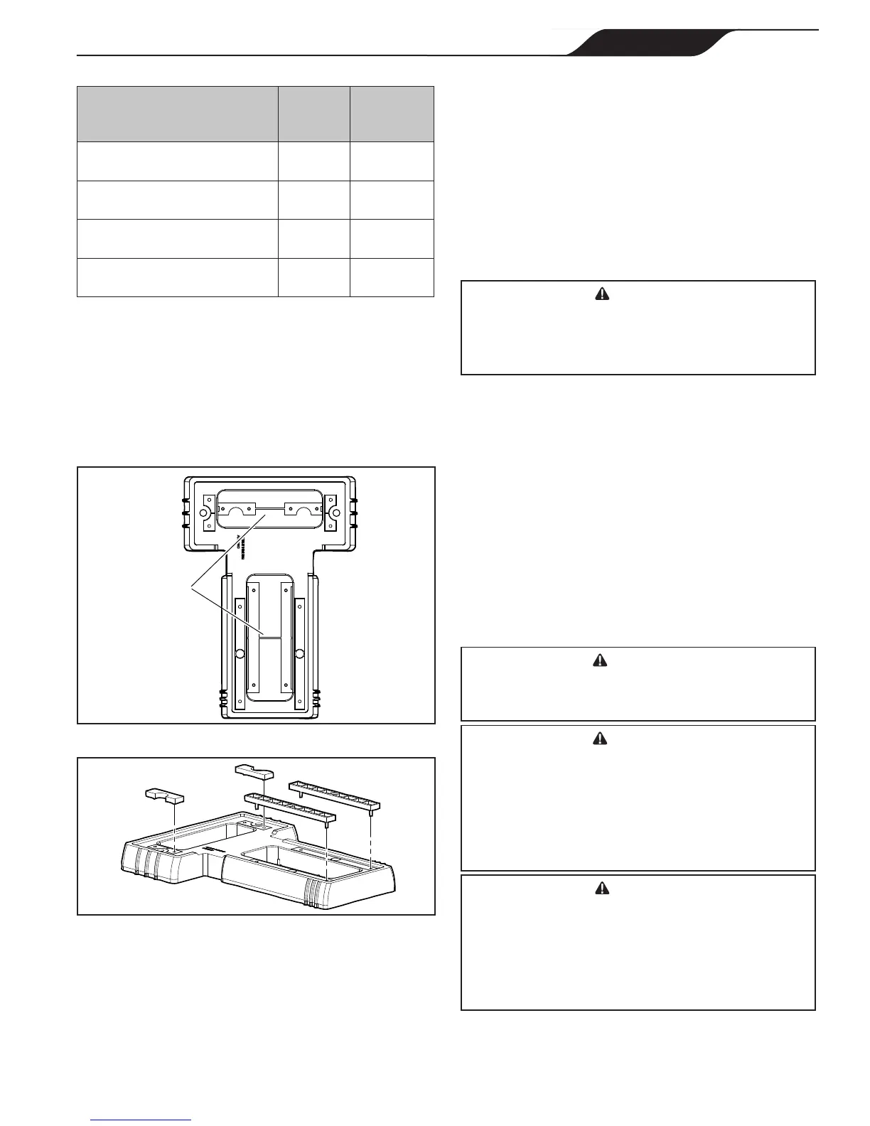
Install Spacers into Small Base
1. Using a hand cutter tool, cut the plastic bars
connecting the top and bottom sets of spacers, as
shown in Figure 4.
2. Push the two (2) top spacers and two (2) bottom
spacers out of the base.
3. Align the pins in the four (4) spacers with the holes
in the base and snap the spacers into place, as
shown in Figure 5.
X
X
Cut
spacers
at X.
Figure 4. Cut Sets of Spacers Out of Base
Figure 5. Snap Spacers into Place
3.2 Electrical Installation
Voltage Checks
The correct voltage, as specied on the pump data plate and
Table 3 on page 10 is necessary for proper performance and
long motor life. Incorrect voltage will decrease the pump’s
ability to perform and could cause overheating, reduce the
motor life, and result in higher electric bills.
 Loading...