Page 10
ENGLISH
Jandy
®
Pro Series VS FloPro™ Series Variable-Speed Pump
|
Installation & Operation Manual
PDA (Rev 4.0 or later), or the AquaLink Z4. The VS
FloPro variable-speed pump communicates with the
controllers via a four-wire RS-485 interface.
VS-FHP1.0 Controller Installation Options
The VS-FHP1.0 Pump comes pre-congured with
the JEP-R variable-speed controller installed and the
DIP switch settings pre-congured to work with this
controller. Review the following instructions if using
the AquaLink RS, AquaLink PDA, or AquaLink Z4
controller, or if remote mounting the JEP-R.
To install an AquaLink RS controller (Rev O or
later), an AquaLink PDA (Rev 4.0 or later), or an
AquaLink Z4:
1. Remove power from the VS FloPro pump by
disconnecting the high voltage lines or by opening
any breaker to which the VS FloPro pump power is
connected.
WARNING
ELECTRICAL SHOCK HAZARD
Turn off all switches and the main breaker in the variable-
speed pump electrical circuit before starting the procedure.
Failure to comply may cause a shock hazard resulting in
severe personal injury or death.
2. Remove the one (1) screw and access cover to
complete electrical connections to the motor.
3. For the VS-FHP1.0, slide dip switches 1 and 2
down to the OFF position, and 5 up to the ON
position. See Figure 7.
Note: VS-FHP1.0 has an additional DIP switch setting 5.
4. Select the desired address(es) for the VS-FHP1.0
pump by setting dip switches 3 and/or 4, as shown in
Section 3.3, VS FloPro Pump Dip Switch Settings.
5. Disconnect the RS485 cable from the 4-pin header on
the pump drive.
Note: Do not cut the cable, or you will lose the ability to return
to the default factory configuration.
6.
Connect the new RS-485 cable from the AquaLink
through the available compression tting and route
the 4-conductor cable through the motor drive
threaded port closest to the connector. Figure 7.
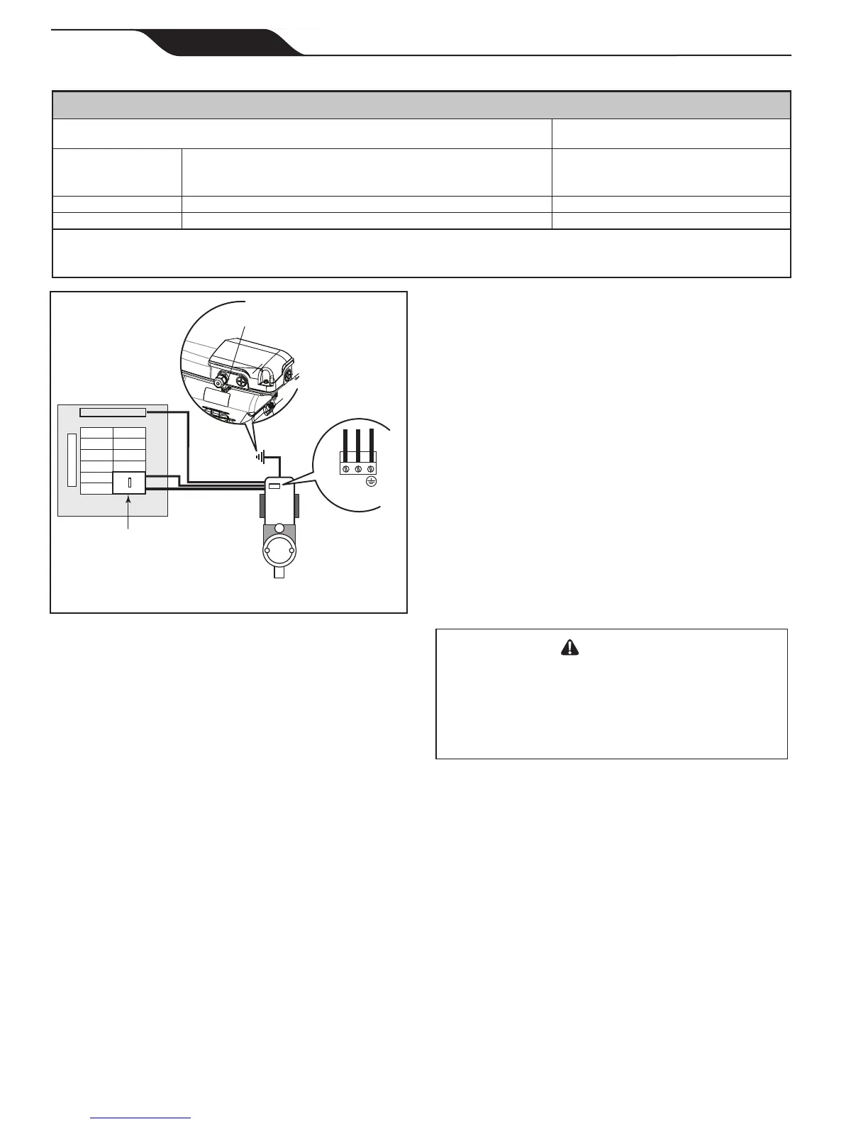
GROUND
NEUTRAL
Breaker Panel
GFCI
Variable-Speed
Pump (230 VAC)
L1
L2
Terminal Block
Bonding Lug
Figure 6. Bonding the Motor
Electrical Wiring
1. The pump motor must be securely and adequately
grounded using the green screw provided. Ground
before attempting to connect to an electrical power
supply. Do not ground to a gas supply line.
2. Wire size must be adequate to minimize voltage
drop during the start-up and operation of the pump.
See Table 3 for suggested wire sizes.
3. Insulate all connections carefully to prevent
grounding or short-circuits. Sharp edges on
terminals require extra protection. For safety, and to
prevent entry of contaminants, reinstall all conduit
and terminal box covers. Do not force connections
into the conduit box.
NOTE Since the pump is operated by either a variable
speed controller (JEP-R), an AquaLink
®
RS controller, an
AquaLink Pool Digital Assistant (PDA), or an AquaLink
Z4, the pump will not be turned on until it is turned on
with one of these controllers.
VS FloPro Controller Options
The VS FloPro pump can be operated by one (1) of four
(4) controllers: the JEP-R variable-speed controller, the
AquaLink RS controller (Rev O or later), the AquaLink
Table 3. Recommended Wire Sizes for VS FloPro Pumps
RECOMMENDED MINIMUM WIRE SIZE FOR VS FLOPRO PUMPS*
Distance from Sub-panel
0-150 Feet
(0-45 metres)
Model
Branch Fuse AMPS
Class: CC, G, H, J, K, RK, or T
Gauge of Wire
Voltage
230 VAC230 VAC
VS-FHP1.0 15A 12
VS-FHP2.0 20A 10
*Assumes three (3) copper conductors in a buried conduit and 3% maximum voltage loss in branch circuit. All National Electrical Code
®
(NEC
®
) or the Canadian Electrical Code (CSA) and local codes must be followed. Table shows minimum wire size and branch fuse
recommendations for typical installation.
 Loading...