Page 11
ENGLISH
Jandy
®
Pro Series VS FloPro™ Series Variable-Speed Pump
|
Installation & Operation Manual
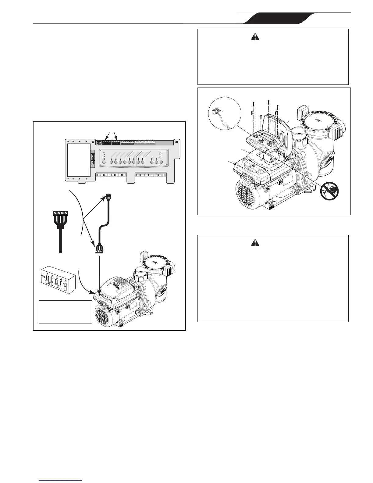
7. Connect the other end of the cable to an RS-485
connector on the AquaLink
®
RS (or multiplexer
interface board), matching wire colors with
connector positions as follows: 1-red, 2-black,
3-yellow, and 4-green. See Figure 7.
8. Restore power to the VS-FHP1.0 pump and verify
the operation of the controller.
9. Refer to the appropriate manual for set up and
operation of the pump: AquaLink RS Owner’s
Manual, 6593, AquaLink PDA Owner’s Manual,
H0572300, or AquaLink Z4 Owner’s Manual,
H0386600.
Variable-Speed
Pump
4321
RED
BLACK
YELLOW
GREEN
RS485
Cable
BLACK
YELLOW
RED
GREEN
Connect to
AquaLink RS
RS-485 Connector
(or Multiplexer
Interface Board)
S1
S2
RESET
SERVICE
TIME OUT
FILTER PUMP
AUX 1
AUX 2
AUX 3
AUX 4
AUX 5
AUX 6
AUX 7
RS6 & RS8 ONLY
RS8 ONLY
HEATER
SOLAR
POOL MODE
SPA MODE
SPA DRAIN
SPA FILL
AUTO
654321
10 9876 54321
4321
4321
AquaLink
®
RS RS-485 Connectors
5-Position
DIP Switch
200 ft (61 m)
max install distance
for communication
Figure 7. Wiring AquaLink RS Controller or
AquaLink PDA to VS-FHP1.0 Pump
VS-FHP1.0 Remote Mounting
The variable-speed controller may be remote mounted
onto a vertical surface that is protected from the
elements.
Follow the directions carefully to maintain the ability
to reinstall the variable-speed controller onto the VS-
FHP1.0 Pump. Reverse these instructions to complete
the reinstallation. See Figure 8.
WARNING
ELECTRICAL SHOCK HAZARD
Turn off all switches and the main breaker in the variable-
speed pump electrical circuit before starting the procedure.
Failure to comply may cause a shock hazard resulting in
severe personal injury or death.
Controller Rear
Loosen
to remove
(x4)
Pump
Motor
Cover
RS-485 Cable
DO NOT CUT
Controller
Base
Access Cover
Figure 8. Disconnect Variable-Speed Controller
from VS-FHP1.0 Pump
WARNING
When determining routing and protection for the
variable-speed controller cabling, ensure that all
National Electrical Code
®
(NEC
®
) and all local code
requirements are met. NEC code requirements
prohibit the routing of signal cables in conduits or
raceways that are used for branch, feeder, or service
conductors. NEC also provides direction for building-
to-building routing of signal cables, with regard to
lightening protection.
At the VS-FHP1.0 pump:
1. Remove power from the VS-FHP1.0 pump by
disconnecting the high voltage lines or by opening
any breaker to which the VS-FHP1.0 pump power
is connected.
2. Lift up the controller cover on its hinges to access
the variable-speed controller.
3. Remove the six (6) screws to disconnect the
variable-speed controller from the controller base
on the VS-FHP1.0 Pump motor.
4. Detach the RS-485 cable connecting the variable-
speed controller user interface to the controller base
on the motor. Do not over extend the cable when
raising the controller away from the motor.
5.
Unscrew the four (4) connector terminals and
disconnect the wires of the motor cable assembly.
Note: Do not cut the cable, or you will lose the ability to
return to the default factory configuration.
 Loading...