Page 12
ENGLISH
Jandy
®
Pro Series VS FloPro™ Series Variable-Speed Pump
|
Installation & Operation Manual
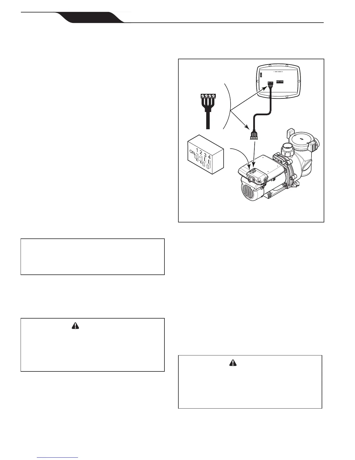
6. For the VS-FHP2.0, slide dip switches 1 and 2 up,
so they are in the ON position, and slide switches
3 and 4 down, so they are in the OFF position. See
Figure 9.
BLACK
YELLOW
RED
GREEN
RS485
4321
RED
BLACK
YELLOW
GREEN
REMOTE CONTROL
54321
INPUT 2
INPUT 3
INPUT 4
COMMON
INPUT 1
4-Position
DIP Switch
Pump
NOTE The VS-FHP2.0 pump comes with a
factory installed four-wire RS-485 cable.
Controller
(Rear View)
RS485
Cable
Figure 9. Wiring Variable-Speed Controller (JEP-R)
to VS-FHP2.0 Pump
7. Connect the other end of the cable to the controller.
Match the colors of the wires with the appropriate
connector positions as follows: 1- red, 2- black, 3-
yellow, and 4- green.
8. Restore power to the VS-FHP2.0 pump and verify
the operation of the controller.
9. Refer to the Variable-Speed Controller Owner’s
Manual, H0412200, to operate the pump.
To install an AquaLink
®
RS controller (Rev O or
later), an AquaLink PDA (Rev 4.0 or later), or an
AquaLink Z4:
1. Remove power from the VS-FHP2.0 pump by
disconnecting the high voltage lines or by opening
any breaker to which the VS-FHP2.0 pump power
is connected.
WARNING
ELECTRICAL SHOCK HAZARD
Turn off all switches and the main breaker in the variable-
speed pump electrical circuit before starting the procedure.
Failure to comply may cause a shock hazard resulting in
severe personal injury or death.
6. Bundle the loose wire into the pocket of the
controller base. This wire will be used if
reinstalling the variable-speed controller onto the
VS-FHP1.0 Pump.
7. Secure the pocket cover and gasket with six (6)
screws to the variable-speed controller base on the
motor.
8. Remove the one (1) screw and access cover to
complete electrical connections to the motor.
9. Insert the free end of the new RS-485 cable through
the available compression tting and route the
4-conductor cable through the motor drive threaded
port closest to the connector.
10. Prepare the cable and attach another 4-pin
connector, ensuring the wire colors match Figure 7.
11. Insert the RS-485 connector onto the corresponding
RS-485 connector on the motor PCB.
12. Secure the compression tting nut around the cable
to secure the motor.
13. Verify the DIP switch settings match Figure 7.
14. Reinstall the access cover with the single screw
removed in step 8.
Follow the instructions in the Variable-Speed Controller
User Interface Installation/Owner’s manual (H0412200)
to complete the remote mounting of the controller.
VS-FHP2.0 Controller Installation Options
To install the JEP-R variable-speed controller:
IMPORTANT
The installer must TURN ON switches 1 and 2 at the
VS-FHP2.0 pump when connected to the variable-
speed controller.
NOTE The variable-speed controller part no. is JEP-R.
1. Remove power from the VS-FHP2.0 pump by
disconnecting the high voltage lines or by opening
any breaker to which the VS-FHP2.0 pump power
is connected.
WARNING
ELECTRICAL SHOCK HAZARD
Turn off all switches and the main breaker in the variable-
speed pump electrical circuit before starting the procedure.
Failure to comply may cause a shock hazard resulting in
severe personal injury or death.
2. Remove the cover of the VS-FHP2.0 junction box
and feed the RS-485 cable into the tting.
3. Unplug the RS-485 connector from the VS-FHP2.0
4. Attach the four (4) wires in the RS-485 cable to
the RS-485 connector. Match the wire colors with
the positions on the connector: 1- red, 2- black, 3-
yellow, and 4- green. See Figure 9.
5.
Insert the RS-485 connector back into the VS-
FHP2.0.
 Loading...