40
UMG 604
+
-
S2
S1
24V
=
4,4k
19
Digital
Input 1
3,9V
3,9V
20
21
Digital
Input 2
4,4k
+
-
24V
DC
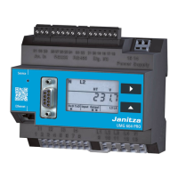
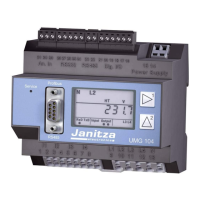
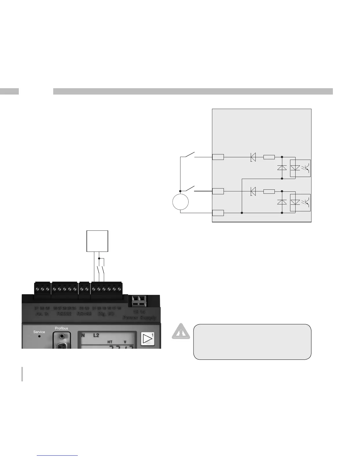
Digital inputs
The UMG604 has 2 digital inputs to each of
which you can connect one transducer.
An input signal is detected at a digital input if a
voltage of at least 10 V and maximum 28 V is
applied. In this case a current of at least 1 mA
and maximum 6 mA flows. Cables longer than
30 m must be laid with shielding.
Please mind the polarity of the feeding volt-
age.
Fig. 40.2 Example for the connection of
external switching contacts S1 and S2 to the
digital inputs 1 and 2.
UMG604
Digital inputs 1-2
Fig. 40.1 Connection example.
m
Attention!
The polarity of the feeding voltage
must be respected for the digital
inputs.
 Loading...