Do you have a question about the janitza UMG 96 and is the answer not in the manual?
| Power Measurement | Active, reactive, apparent power |
|---|---|
| Power Factor Measurement | Yes |
| Frequency Measurement Range | 45 - 65 Hz |
| Accuracy Class | 0.5S (IEC 62053-22) |
| Energy Measurement | Active, Reactive Energy |
| Communication Interfaces | RS-485, Ethernet |
| Power Supply | 85...265 V AC/DC |
| Protection Class | IP20 |
| Dimensions | 96 x 96 x 78 mm |
Details the items that always belong to the contents of delivery, including the device and operating instructions.
Describes the UMG96's suitability for low voltage switchgear and measurement of voltage, current, and power.
Emphasizes that the device must be installed and used by qualified personnel according to safety regulations.
Explains the UMG96's three-phase measurement system, scanning process, and internal temperature correction for display.
States that repairs and calibration can only be performed by the manufacturer to maintain device integrity.
Provides instructions for cleaning the front foil using a soft cloth and mild cleansing agent, avoiding acidic agents.
Instructs to dispose of the UMG96 as electronic waste according to legal regulations and ensure recycling.
States the UMG96 is suitable for fixed installation in low and medium voltage switchgear with any mounting position.
Details connection requirements for three-phase systems and required voltage ranges for proper operation.
Explains current measurement via current transformers and warns about the live nature of the inputs.
Describes setting the total transformer ratio for sum current measurement using multiple current transformers.
Instructions for mounting the device, ensuring net conditions match the type plate information.
Details voltage varieties and connection wire suitability for measurement and supply voltage connection.
Explains how to set current transformer ratios and voltage transformer ratios for the device's configuration.
Describes connecting current transformers to the device and verifying the ratio with an Amperemeter.
Addresses issues with a dark display, suggesting fuse check or potential device defect.
Explains how to add the required measured value indication if it was deleted from the selection.
Recommends checking connection, programming, or using different current transformers if current is incorrect.
Advises checking connections and ensuring measuring inputs are not overloaded for correct voltage indication.
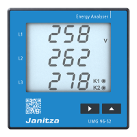
Explains how to scroll through measured values using keys 1 and 2 in the device's indication mode.
Describes how measurements are taken, averaged, and how changes reflect on the display over time.
Details averaging times for currents and power, indicated by a horizontal bar above the displayed value.
Explains the energying hours meter detects operation time with a resolution of 15 minutes.
Describes how to enter programming mode using keys 1 and 2, and the necessity of a password.
Provides an example of programming for sum current measurement using two different current transformers.
Details the steps to program voltage transformer settings, including primary voltage and decimal point adjustment.
Describes how outputs function as switching outputs for measured values, switching based on set limits.
Explains how outputs function as pulse outputs for energy measurement, with pulse valency and frequency limits.
Details how to program outputs K1 or K2 as pulse outputs, including setting the pulse valency.
Provides an example calculation for setting pulse valency based on power consumption and desired pulse rate.
Details how to program the minimum pulse width for pulse outputs using keys 1 and 2.
Explains the exponential method used to calculate mean values, reaching 95% of the measured value.
Details how to program averaging times for real power and current measurements.
Details how to program the rotation time for automatic measured value indication on the display.
Details how to program measured value selection and automatic rotation settings for display indication.
Details how to program the LCD contrast setting using keys, adjusting display readability.
Lists ambient conditions such as temperature, pollution degree, humidity, and protection class for operation.
Provides technical specifications for measurement and supply voltage, inputs, and current/voltage ranges.
Details technical specifications for outputs, including type, switching frequency, operating current, and voltage.
Specifies the types and sizes of connectable cables, including wire types and pin contact requirements.
Provides a quick guide on how to select and program the current transformer settings via the menu.
Explains how to call up and scroll through measured values using keys 1 and 2 when not in programming mode.