Do you have a question about the janitza UMG96L and is the answer not in the manual?
| Current Measurement | Yes |
|---|---|
| Frequency Range | 45 - 65 Hz |
| Operating Temperature | -10°C to +55°C |
| Mounting | Panel mounting |
| Measurement Category | CAT III |
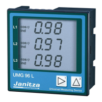
| Power Measurement | Active, Reactive, Apparent |
| Energy Measurement | Active, Reactive, Apparent (Import/Export) |
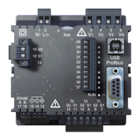
| Communication Interfaces | RS485 |
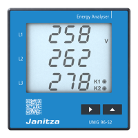
| Display | LCD |
| Current Range | Dependent on CTs used |
| Accuracy | Class 0.5 |
Lists the items included in the product package.
Information on authorized repair and calibration services.
Specific instructions for cleaning the device's front display.
Guidance on environmentally friendly disposal of the device.
Specifies the applications and environments for which the device is designed.
Explains how the UMG96L measures and processes electrical data.
Details suitable locations and methods for installing the device.
Specifies voltage connection requirements and safety precautions.
Details the precision and potential errors in current measurements.
Explains the smallest detectable current changes.
Information on measuring very low current values.
Shows a four-wire measurement setup with three current transformers.
Depicts a four-wire measurement with two current transformers.
Illustrates measurement using three voltage and three current transformers.
Shows measurement with three voltage and two current transformers.
Guides on connecting the device to power and measurement voltages.
Instructions for setting transformer ratios for accurate measurements.
Verifies correct connection of phase conductors to current transformers.
Ensures correct direction of power flow is detected.
Confirms accuracy of voltage and current inputs for power calculation.
Validates correct power measurement per phase.
Verifies the total power calculation across all phases.
How to view measured values using the device's keys.
Accessing and modifying device settings and parameters.
Step-by-step guide to setting the current transformer parameters.
Instructions for configuring voltage transformer settings.
Configuration steps for setting averaging times for power and current.
Setting the interval for automatic cycling through measured values.
Configuring the automatic display of selected measurement values.
Steps to set the LCD contrast level.
Procedure for programming and managing the user access password.
General safety requirements for electrical equipment.
Specifications for electrical test voltages applied to the device.
Details on electromagnetic compatibility and immunity standards.
Environmental operating and storage parameters for the device.
Technical details on measurement inputs, voltages, and current capabilities.
Information on wire types and terminal connections for cabling.
Shows a four-wire measurement setup with three current transformers.
Step-by-step procedure to set the current transformer ratio.
How to navigate and view different measured data on the display.